Image forming apparatus

a technology of forming apparatus and forming chamber, which is applied in the direction of electrographic process apparatus, printing, instruments, etc., can solve the problem of more than a conventional time delay in the cleaning cycle, and achieve the effect of reducing the time for cleaning

Inactive Publication Date: 2009-11-24
SHARP KK
View PDF5 Cites 4 Cited by
  • Summary
  • Abstract
  • Description
  • Claims
  • Application Information

AI Technical Summary

Benefits of technology

[0012]The present invention is accomplished in view of the above-mentioned circumstance, and aims to provide a technique capable of delaying a period for cleaning, compared to a conventional case, even if a reflection surface of a polygon mirror becomes dirty as it is used.

Problems solved by technology

Accordingly, even if the reflection surface of the polygon mirror becomes dirty as it is used, a cleaning cycle is delayed more than a conventional time.

Method used


Image

  • Image forming apparatus
  • Image forming apparatus
  • Image forming apparatus

Examples


case 1

D sensor signals at scanning terminal end and at scanning start end are detected

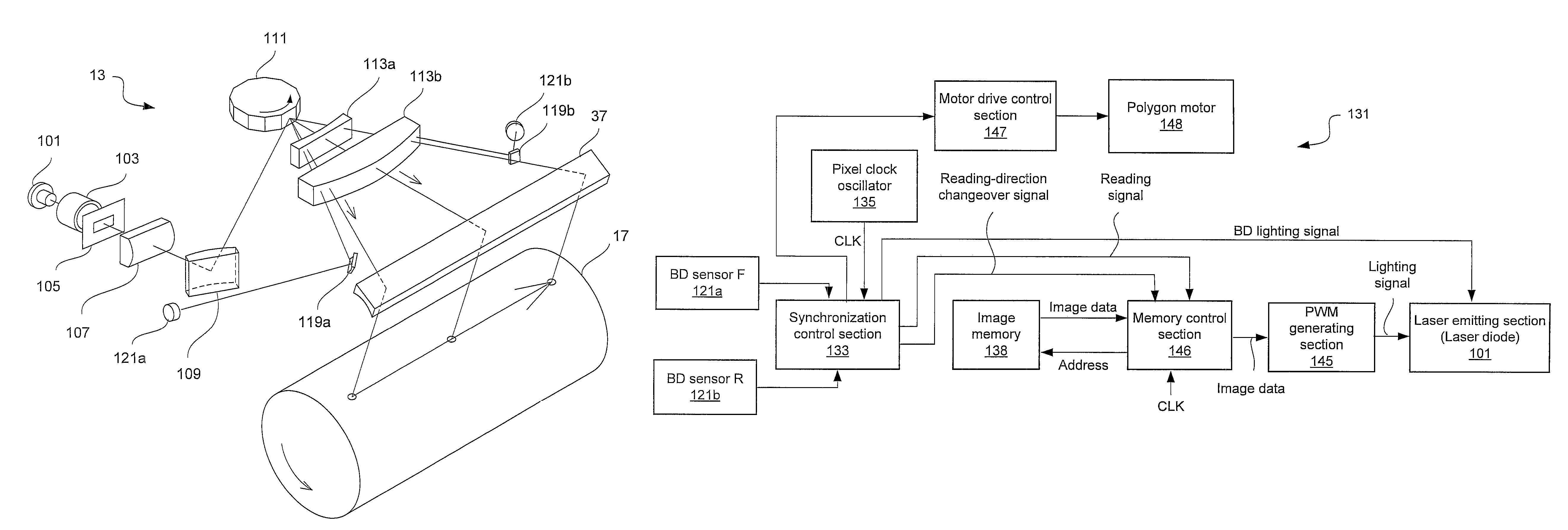
[0076]This is a case in which the rising edge L2 of the second signal pulse is detected during time t1 from the time D1 that is a falling timing of the first signal pulse of the BD sensor signal, as shown in FIG. 9B.

[0077]This case is considered, since the output level of the BD sensor is unstable.

[0078]In this case, the BD lighting signal is temporarily turned OFF after the predetermined number of pixel clocks from the time L2, and then, the BD lighting signal is turned ON after the time T0 has elapsed from the time L2. Accordingly, the BD sensor signal at the scanning terminal end is masked. Thereafter, the BD lighting signal is temporarily turned OFF after the predetermined number of pixel clocks from the rising time L1 of the BD sensor signal, and then, the BD lighting signal is turned ON after the time T0 has elapsed from the time L1. This control is repeated, whereby only the detection signal at th...

case 2

he BD sensor signal at scanning start end is detected

[0079]This is a case in which the rising edge L2 of the second signal pulse is not detected during the time t1 from the time D1 that is the falling timing of the first signal pulse of the BD sensor signal, as shown in FIG. 9C.

[0080]In this case, the BD lighting signal is temporarily turned OFF after the predetermined number of pixel clocks from the rising time L1 of the first signal pulse, and then, the BD lighting signal is turned ON after the time T0 has elapsed from the time L1. Accordingly, the BD sensor signal at the scanning terminal end is masked. Thereafter, the BD lighting signal is temporarily turned OFF after the predetermined number of pixel clocks from the rising time L1 of the next BD sensor signal, and then, the BD lighting signal is turned ON after the time T0 has elapsed from the time L1. This control is repeated, whereby only the detection signal at the scanning start end can be obtained.

[0081]A modification of t...


PUM


Abstract

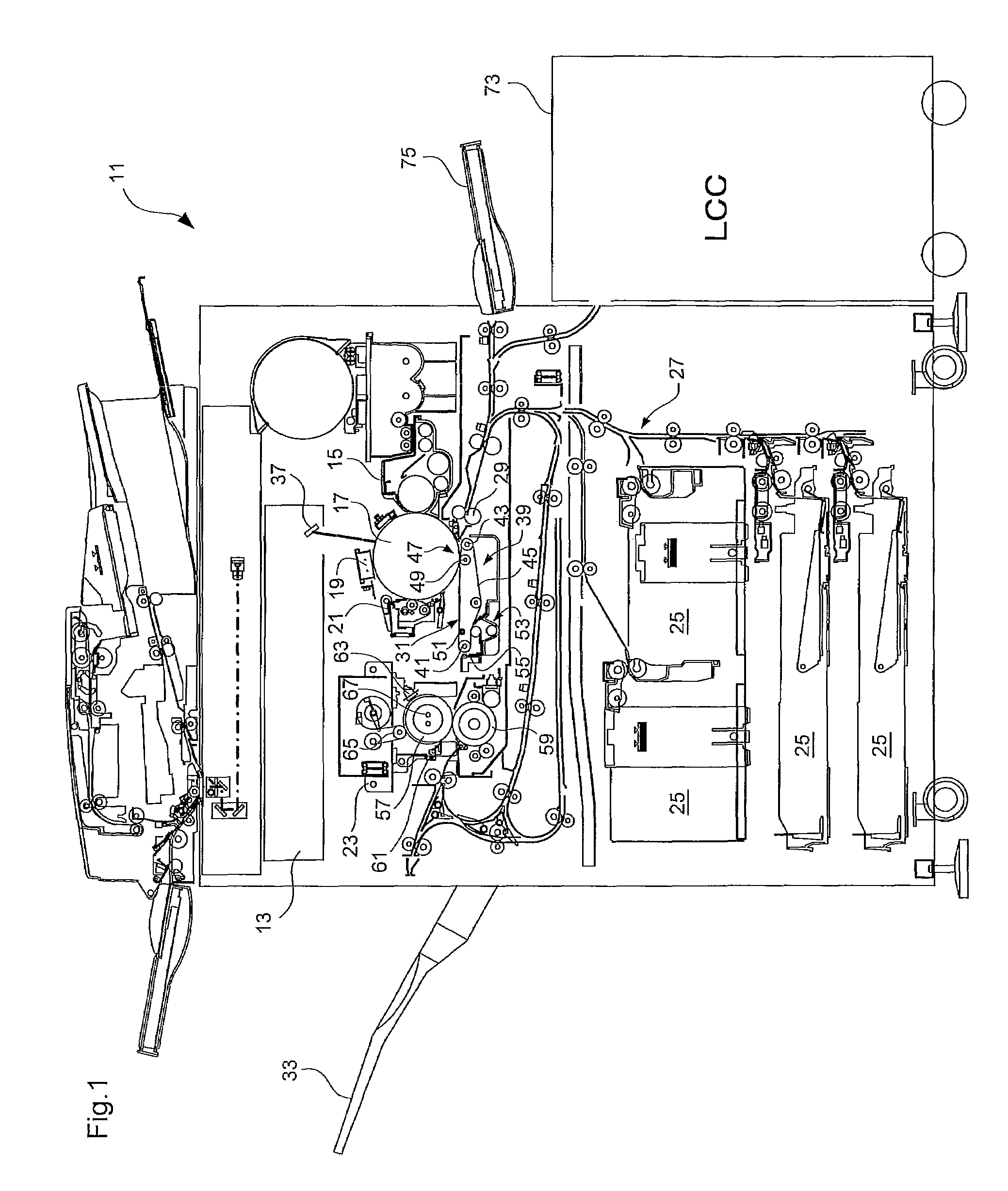
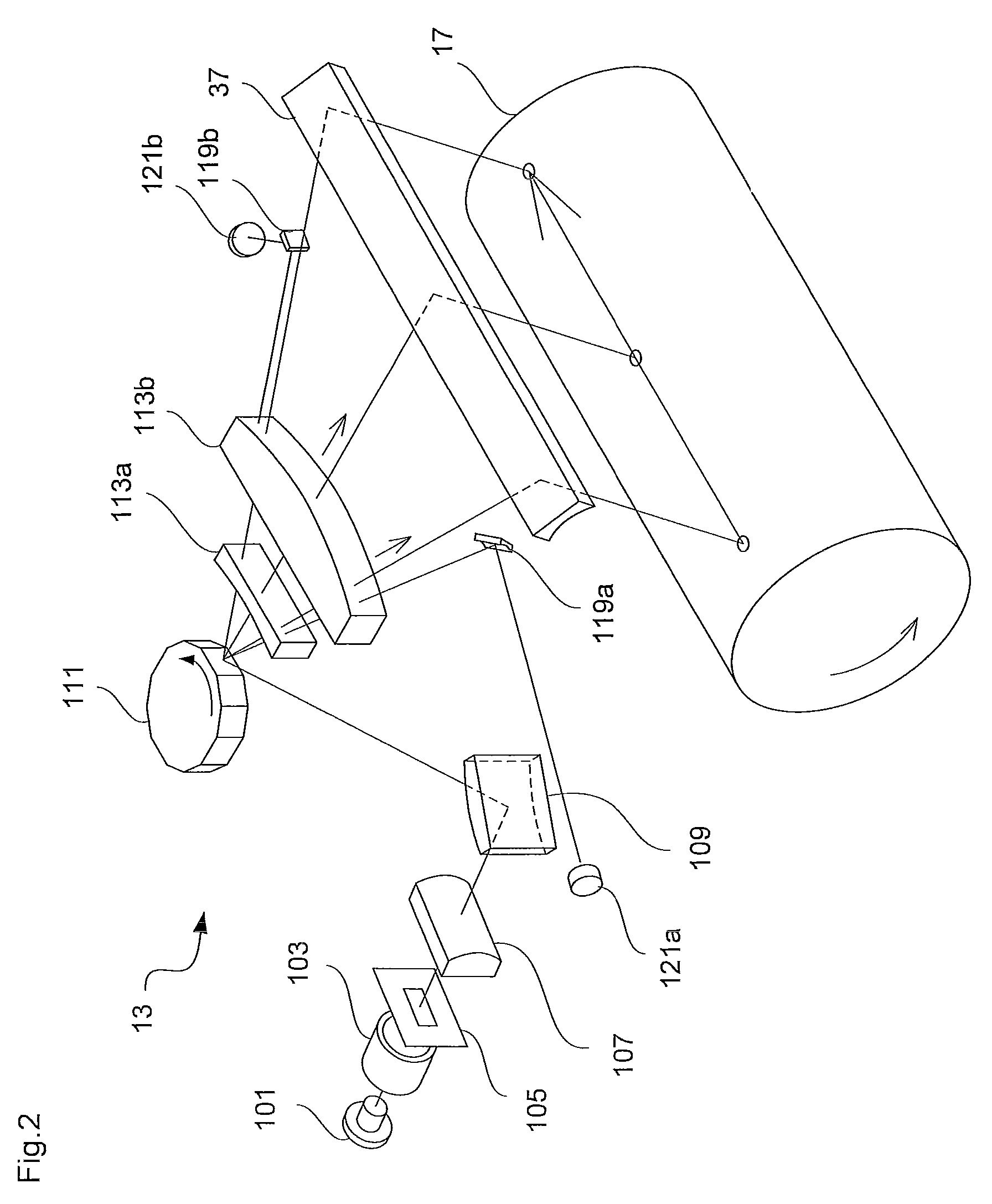
An image forming apparatus including: a polygon motor that rotates a reflection member; a laser emitting section that emits a laser beam toward a side face of the rotating reflection member; a photoconductor that is scanned by a laser beam reflected from the side face of the reflection member; a beam detecting section that detects a scanning start position of the reflected laser beam, and a scanning final position; and a control section that controls the polygon motor and the laser emitting section, based on detection signals from the beam detecting section, wherein when the detection signal at the scanning start position does not meet a predetermined time-based standard and / or a predetermined output-level standard, the control section controls the polygon motor so that the reflection member rotates in a reverse direction.

Description

CROSS-REFERENCE TO RELATED APPLICATION[0001]This application is related to Japanese Patent Application No. 2008-097129 filed on Apr. 3, 2008, whose priority is claimed and the disclosure of which is incorporated by reference in its entirety.BACKGROUND OF THE INVENTION[0002]1. Field of the Invention[0003]The present invention relates to an image forming apparatus in which a photoconductor is exposed by a laser beam.[0004]2. Description of the Related Art[0005]There has been known, as an electrophotographic image forming apparatus, an apparatus in which a surface of a photoconductor is scanned and exposed by a laser beam. A general mechanism for scanning the laser beam includes a rotating reflection member (polygon mirror), wherein a laser beam emitted from a laser source, which is located at a fixed position, is reflected on the rotating reflection member so as to be deflected in a predetermined direction according to a change in a reflection angle caused by a rotation of the reflect...

Claims


Application Information

Patent Timeline
Patent Type & Authority Patents(United States)
IPC IPC(8): G02B26/08B41J27/00
CPCG03G15/043G03G15/04072G03G15/0435G03G2215/0404
Inventor ODA, AYUMU
Owner SHARP KK
Why Eureka
Try Eureka