Digital-to-analog converter circuit and data driver

a digital-to-analog converter and data driver technology, applied in the field of digital-to-analog converter circuits and data drivers, can solve the problems of image degradation, non-ignorance of the change speed of the input voltage of the amplifier circuit, and generation circuits increasing the chip size (manufacturing cost) of the data driver, so as to improve the display quality, shorten the delay period caused by parasitic capacitance at the input unit of the amplifier circuit, and improve the effect of the parasi

Active Publication Date: 2020-12-15
LAPIS SEMICON CO LTD
View PDF16 Cites 1 Cited by
  • Summary
  • Abstract
  • Description
  • Claims
  • Application Information

AI Technical Summary

Benefits of technology

[0057]Accordingly, a delay period caused depending on a parasitic capacitance at an input unit of the amplifier circuit can be shortened compared with a case of a conventional digital-to-analog converter circuit where one selection voltage is supplied to every input terminal of the amplifier circuit regardless of the contents of the digital data signal. Thus, the delay of the change speed of the output voltage of the amplifier circuit is improved in the worst case, and uniforming the change speed of the output voltage of the amplifier circuit for each gradation level can be ensured. This improves the display quality.

Problems solved by technology

However, increasing the number of the reference voltages generated in the reference voltage generation circuit increases a chip size (manufacturing cost) of the data driver by the amount of the increased number of reference voltages.
The charging percentage of the data lines lower than the predetermined value causes an image degradation, such as an uneven luminance.
However, because of the shortened one data period in association with the higher definition display panel, the change speed of the input voltage of the amplifier circuit has become non-ignorable.
The change speed of the input voltage of the amplifier circuit influences a change speed of the output voltage of the amplifier circuit, and the decreased charging percentage of the data line (finally, a charging percentage of an electrode inside the display cell) causes the degradation of the quality of the panel display.
Accordingly, a problem arises in that the change of the output voltage of the amplifier circuit is also slowed.
Therefore, the interpolation can be applied to the range B, while the interpolation is not appropriate for the range A because the interpolation in the range A increases error.
Therefore, in accordance with this, a problem arises in that the change of the output voltage of the amplifier circuit is also slowed.
Therefore, in the range B, a problem arises in that the change speed of the output voltage of the amplifier circuit differs for each gradation level.
These problems cause the degradation of the display quality, such as a decrease in luminance and an uneven display.

Method used


Image

  • Digital-to-analog converter circuit and data driver
  • Digital-to-analog converter circuit and data driver
  • Digital-to-analog converter circuit and data driver

Examples


example 1

[0095]FIG. 5 is a block diagram illustrating a configuration of a digital-to-analog converter circuit (also referred to as a DA converter circuit) of a RDAC system according to the present invention that includes the converter circuit DC1 and the reference voltage generation circuit 10 extracting the converter circuit DC1 among the converter circuits DC1 to DCn illustrated in FIG. 4.

[0096]The reference voltage generation circuit 10 includes a ladder resistor LDR that receives, for example, a predetermined electric potential VGH and an electric potential VGL lower than the electric potential VGH, and divides a voltage between the electric potentials VGH and VGL into a plurality of voltages having mutually different voltage values. The reference voltage generation circuit 10 classifies the plurality of divided voltages divided by the ladder resistor LDR as follows, thus generating the first reference voltage group VX and the second reference voltage group VZ.

[0097]A plurality of refer...

example 2

[0132]FIG. 9 is a block diagram illustrating another exemplary configuration of the second decoder 40 included in the converter circuit DC. In FIG. 9, since the reference voltage generation circuit 10, the amplifier circuit 20, and the first decoder 30 included in the DA converter circuit are same as those illustrated in FIG. 5, descriptions for them are omitted.

[0133]In the configuration illustrated in FIG. 9, the second bit signal group BT2 is further divided into a first sub-bit signal group b1, a second sub-bit signal group b2, and a third sub-bit signal group b3.

[0134]Furthermore, in the configuration illustrated in FIG. 9, the second decoder 40 includes a first sub-decoder 41 that receives the first sub-bit signal group b1 and a second sub-decoder 42 that receives the second sub-bit signal group b2.

[0135]The first sub-decoder 41 selects two different selection voltages (VC, VD) without an overlap from the second reference voltage group VZ corresponding to the first sub-bit sig...

example 3

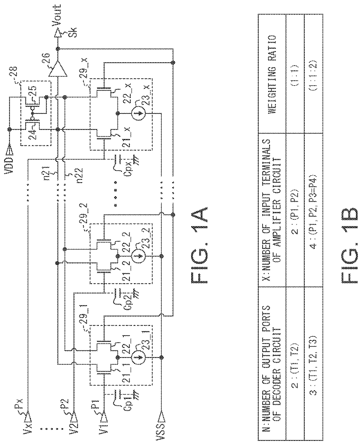
[0139]FIG. 10A and FIG. 10B are drawings illustrating exemplary operations of the decoders (30, 40) in the above-described second selection state (Tc2) as examples of appropriate specifications for the DA converter circuits (10, DC1) according to the present invention.

[0140]FIG. 10A is a drawing illustrating a specification appropriate for a case where the number N of input terminals of the amplifier circuit 20 is N=2, and FIG. 10B illustrates the case of N=3. FIG. 10A and FIG. 10B each illustrate a relationship among the reference voltage Vref selected by the first decoder 30 and the second decoder 40, bit codes (bits D4 to D0) of the data signal, and the selection voltages [V(T1) to V (TN)] input to the terminals T1 to TN of the amplifier circuit 20 in the matching with respective levels indicating the voltage values of the output voltage in stages. The levels 0 to 7 illustrated in FIG. 10A and FIG. 10B correspond to the voltage in the range A, which is inappropriate for the inter...


PUM


Abstract

The present invention includes: a first decoder that outputs mutually different two voltages as first and second selection voltages based on a first bit group of a digital data signal in a first selection state, and outputs one or both of the two voltages as the first and the second selection voltages in a second selection state; a second decoder that outputs mutually different two voltages as third and fourth selection voltages based on a second bit group of the digital data signal in the first selection state and outputs one voltage based on the second bit group as the third and the fourth selection voltages in the second selection state; and an amplifier circuit that averages a combination of the first and the second selection voltages or the third and the fourth selection voltages with predetermined weighting ratios and outputs the averaged voltage.

Description

BACKGROUND1. Technical Field[0001]The present invention relates to a digital-to-analog converter circuit and a data driver for a display device.2. Related Art[0002]Currently, as an active matrix type display device, a liquid crystal display device or an organic EL display device has become a mainstream. The display device includes a display panel, a data driver, and a scanning driver. On the display panel, a plurality of data lines and a plurality of scanning lines are wired in an intersecting manner, and display cells connected to the plurality of data lines via pixel switches are arranged in a matrix. The data driver supplies analog voltage signals corresponding to gradation levels to the plurality of data lines of the display panel. The scanning driver supplies scanning signals that control ON / OFF of respective pixel switches to the plurality of scanning lines of the display panel. The data driver includes a digital-to-analog converter circuit that converts a video digital signal...

Claims


Application Information

Patent Timeline
Patent Type & Authority Patents(United States)
IPC IPC(8): G09G3/20H03M1/66
CPCG09G3/20H03M1/66G09G2310/027G09G2300/0828G09G2310/0291G09G2310/0286H03M1/742H03M1/68G09G2300/0426G09G2320/0252G09G2320/0673G09G3/2003G09G3/3685
Inventor TSUCHI, HIROSHI
Owner LAPIS SEMICON CO LTD
Why Eureka
Try Eureka