
Protective cover for the underside of a vehicle

a protective cover and vehicle technology, applied in the field of protective covers, can solve the problems of inability to incorporate intricate or complex shaping, excessive weight and cost, and insufficient conventional steel protective covers, and achieve the effect of facilitating the attachment of protective covers

Active Publication Date: 2009-12-01
HONDA MOTOR CO LTD
View PDF42 Cites 43 Cited by
  • Summary
  • Abstract
  • Description
  • Claims
  • Application Information

AI Technical Summary

Benefits of technology

The present invention provides a protective cover for vehicles that can be attached to the vehicle and is designed to distribute the load from impact or terrain obstacles in a predetermined manner. The protective cover can be made from plastic and includes a rib that can move from a first position to a second position upon impact. The rib is shaped to matingly contact a feature on the vehicle and to transmit the load to the feature in a safe and effective manner. The fastening portion of the protective cover can include a mounting structure and an abutment structure that contacts a mounting wall on the vehicle to transmit the load. The protective cover can also be attached to the vehicle at an edge portion and include a base and a wall that extends from the base around the base perimeter at a height greater than the predetermined height and width of the base.

Problems solved by technology

However, conventional steel protective covers are inadequate for multiple reasons including, for example, excessive weight and cost, inability to incorporate intricate or complex shaping, complexity of manufacture due to multiple parts being welded together, and requirement for corrosion protection and / or vibration and noise dampening.
However, some conventional plastic protective covers fail to adequately protect features on the underside of a vehicle.
These conventional plastic protective covers have shapes which are similar to those of the steel protective covers which they replace, but have relatively low tolerance for ground contact with rocks and obstacles having sharp edges.
Also, although such protective covers flex readily and generally spring back, if pushed too far, they may tear before taking on much permanent deformation.
However, as conventional plastic protective covers typically have a similar shape to those conventional metal protective covers which they replace, and as conventional plastic protective covers are unable to absorb and transfer loads to a vehicle in the same manner as can conventional steel protective covers, it is typical that such conventional plastic protective covers can crack and / or creep, particularly at the fastening areas, when the conventional plastic protective covers are exposed to impacts from terrain obstacles.
Upon cracking or creeping of a conventional plastic protective cover, the protective cover can lose its ability to protect the underside of a vehicle, the fasteners for the protective cover can lose torque and fall out, the protective cover can vibrate and make noise, and / or the protective cover can become snagged upon terrain obstacles.
Additionally, some conventional plastic protective covers are mounted upon a vehicle with fasteners such that the head of one or more of the fasteners is exposed to damage from contact with underlying objects.
The likelihood of damage to such fasteners is escalated when the protective cover is used on an off-road type of vehicle such as an all terrain vehicle (“ATV”).
Damaged fasteners can perform inadequately to secure a plastic protective cover to a vehicle and additionally can be difficult to remove during maintenance to features of the vehicle which are shielded by the protective cover.
Additionally, damage to fasteners can necessitate replacement of the damaged fasteners, which accordingly results in additional expense to the vehicle's owner.
However, these arrangements are often still susceptible to damage and / or torque loss from ground contact.
However, it is usually difficult to install and remove bolts from such pockets which can thereby make installation and removal of such a protective cover difficult.

Method used


Image

  • Protective cover for the underside of a vehicle
  • Protective cover for the underside of a vehicle
  • Protective cover for the underside of a vehicle

Examples


Embodiment Construction

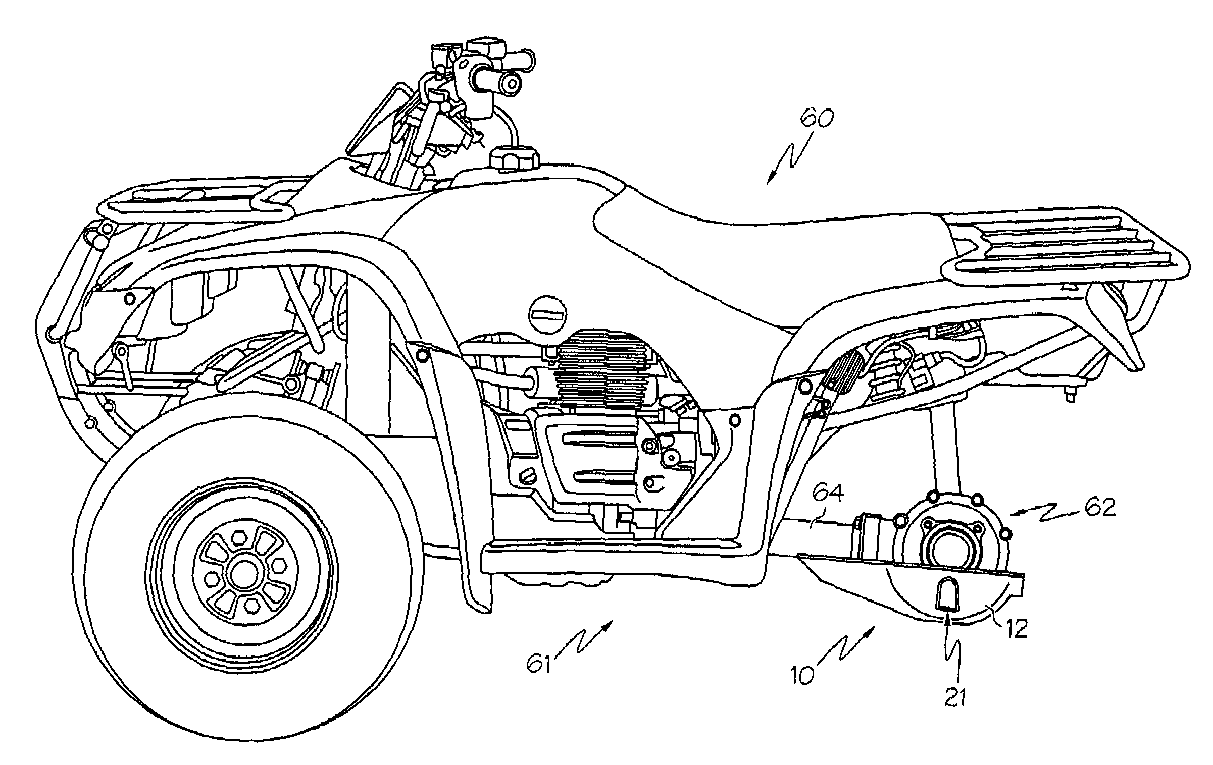
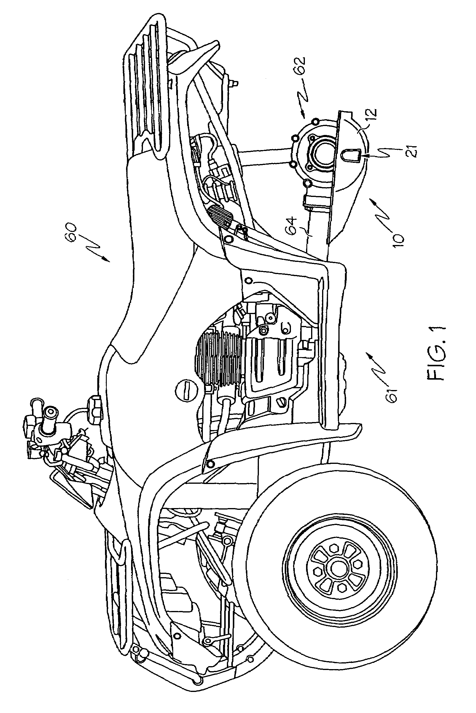
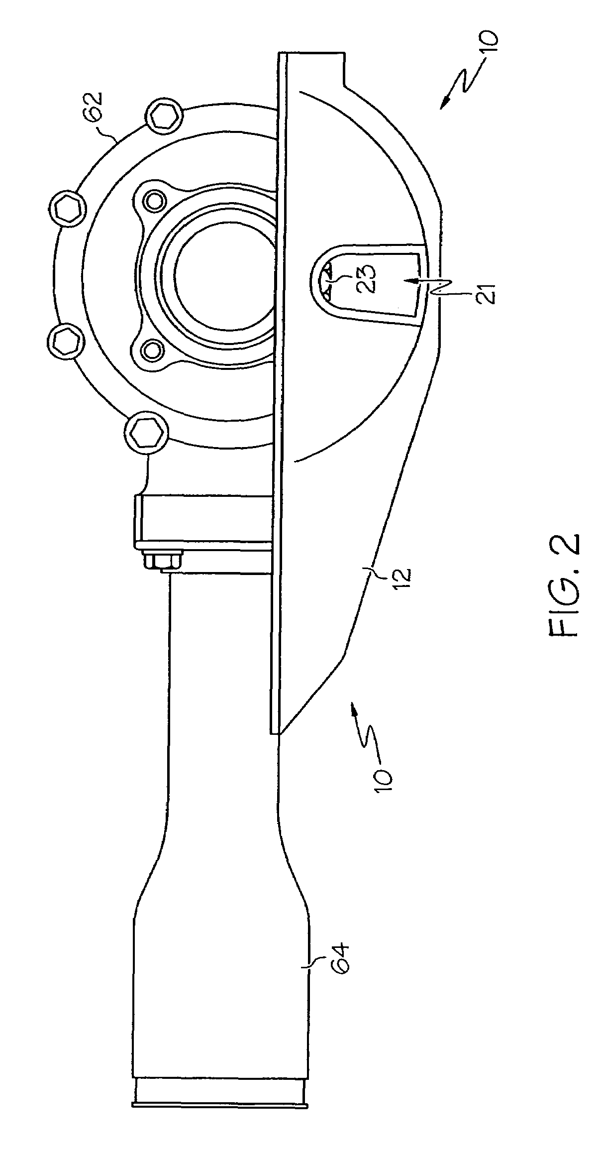
[0024]The present invention and its operation are hereinafter described in detail in connection with the views and examples of FIGS. 1-3, 3A-3B, and 4-9, wherein like numbers indicate the same or corresponding elements throughout the views. A protective cover in accordance with the present invention can be attached to the underside of a vehicle for providing protection for one or more features disposed on or accessible from the underside of the vehicle. For example, a protective cover can be provided upon any of a variety of vehicles including, for example, automobiles, trucks, vans, motorcycles, recreational vehicles, watercraft, aircraft, agricultural equipment, construction equipment, toys, or other power equipment. Features of a vehicle protected by a protective cover can include, for example, a final drive gear case, a transmission, a transfer case, exhaust components, a fuel tank, an oil pan, frame or body elements, and / or any of a variety of other items disposed on or accessi...


PUM


Abstract

A protective cover for the underside of a vehicle is formed substantially from plastic and can provide a skid plate for the vehicle. The protective cover includes at least one fastening portion which is configured to facilitate attachment of the protective cover to the vehicle. In one embodiment, the protective cover includes a rib that is movable to matingly contact a feature on an underside of a vehicle so that loading from an impact is distributed in a predetermined manner. In another embodiment, the fastening portion includes an abutment wall that substantially transmits a shearing load from the protective cover to a vehicle. In yet another embodiment, the fastening portion is adjacent to an edge portion of the protective cover. The protective cover may be included in a vehicle.

Description

TECHNICAL FIELD[0001]The present invention is directed to a protective cover for attachment to the underside of a vehicle. The protective cover can comprise a skid plate to protect one or more components of the vehicle from being damaged by terrain obstacles passing beneath the vehicle.BACKGROUND OF THE INVENTION[0002]It is known to protect the underside of a vehicle with a protective cover formed from stamped sheet metal. The purpose of such a protective cover is to prevent or reduce the consequence of an impact between an object lying on the ground (herein sometimes referred to as a terrain obstacle) and features disposed on the vehicle's underside in circumstances where the ground clearance of the vehicle is insufficient to allow the features to pass thereover without contact. However, conventional steel protective covers are inadequate for multiple reasons including, for example, excessive weight and cost, inability to incorporate intricate or complex shaping, complexity of manu...

Claims


Application Information

Patent Timeline
Patent Type & Authority Patents(United States)
IPC IPC(8): B60K23/00
CPCB62K5/01B62J23/00B60R13/0861
Inventor BOWERS, LEE N.
Owner HONDA MOTOR CO LTD
Learn More