Railroad car draft gear

a technology for drafting gear and cars, applied in the field of railroad cars, can solve the problems of inability to change the size of the draft gear housing, the size of the elastomeric spring assembly used in the draft gear to absorb, and the few options. achieve the effect of cost saving

Active Publication Date: 2009-12-01
MINER ENTERPRISES INC
View PDF6 Cites 31 Cited by
  • Summary
  • Abstract
  • Description
  • Claims
  • Application Information

AI Technical Summary

Benefits of technology

[0007]According to this aspect, and unlike other known spring assemblies, the metal plate at the end of the spring assembly arranged adjacent to the spring seat has been removed and eliminated, thus, resulting in costs savings. The spring seat defines a surface, arranged in direct contacting relation with an end of the spring assembly. The spring contacting surface on the spring seat has an incongruity for limiting radial expansion of an elastomeric pad forming part of the spring assembly and which is arranged in direct contacting relation with the spring seat along at least two axes when an axial load is applied to the wedge of the draft gear.
[0008]In one embodiment, the incongruity on the spring contacting surface of the spring seat is defined by an annular groove concentrically arranged about a longitudinal axis of the draft gear housing. In another form, the incongruity on the spring contacting surface of the spring seat is defined by a series of equi-angularly disposed recesses concentrically arranged about a longitudinal axis of the housing. In still another form, the incongruity on the spring contacting surface of the spring seat can be configured as an annular projection or a series of equi-angularly spaced and shaped projections for gripping and resisting easy outward radial movement of the adjacent elastomer spring.
[0011]According to this aspect, and to reduce the manufacturing cost of the railcar draft gear, the metal plate normally disposed between the end of the multi-tiered spring assembly and the spring seat has been removed and eliminated. A surface on the spring seat, arranged in contacting relationship with the multi-tiered spring assembly, preferably defines at least one incongruity for allowing the elastomer of the spring assembly, arranged adjacent to the spring seat, to deform and operably combine with the incongruity thereby limiting radial expansion of the elastomeric spring arranged in contiguous relation relative to the spring seat.
[0013]The metal plate at the opposite end of the multi-tiered spring assembly, arranged adjacent to the draft gear housing, has also preferably been removed and eliminated, thus, resulting in further costs savings. In one form, a surface on the draft gear housing arranged in contacting relation relative to the spring assembly preferably defines an incongruity for limiting radial expansion of the end of the elastomeric spring when an axial compressive load is applied to the wedge of the draft gear.
[0015]To aid in costs savings, the metal plate normally disposed between the multi-tiered spring and the spring seat has been removed and eliminated. The spring contacting surface on the spring seat, arranged in direct contacting relation with an elastomeric spring at a second end of the spring assembly, defines an incongruity for limiting radial expansion of the elastomeric spring at the second end of the spring assembly along at least two axes. Preferably, the spring contacting surface on the spring seat further defines a central recess for accommodating the protrusion axially extending from the end of the spring assembly so as to advantageously affect and maintain axial alignment of the multi-tiered spring relative to a longitudinal axis of the draft gear housing.
[0017]To further aid in reducing the manufacturing cost of the railroad car draft gear, the metal plate at the opposite end of the multi-tired spring is also eliminated. In this regard, a surface on the draft gear housing arranged in contacting relation relative to the end of the multi-tiered spring assembly defines an incongruity for limiting radial expansion of the adjacent spring when an axial compressive load is applied to the wedge of the draft gear.

Problems solved by technology

When considering costs savings in connection with draft gears, however, the options are few.
First, the size of the draft gear housing cannot be changed without adversely effecting the relationship with a fixed size pocket provided in a railcar centersill in which the draft gear is accommodated.
Moreover, the size of the elastomeric spring assembly used in the draft gear to absorb impacts, as defined by the number of the elastomeric springs comprising the spring assembly, cannot be reduced without adversely effecting draft gear performance and operation.

Method used


Image

  • Railroad car draft gear
  • Railroad car draft gear
  • Railroad car draft gear

Examples


Embodiment Construction

[0036]While the present invention is susceptible of embodiment in multiple forms, there is shown in the drawings and will hereinafter be described preferred embodiments of the invention, with the understanding the present disclosure is to be considered as setting forth exemplifications of the invention which are not intended to limit the invention to the specific embodiments illustrated and described.

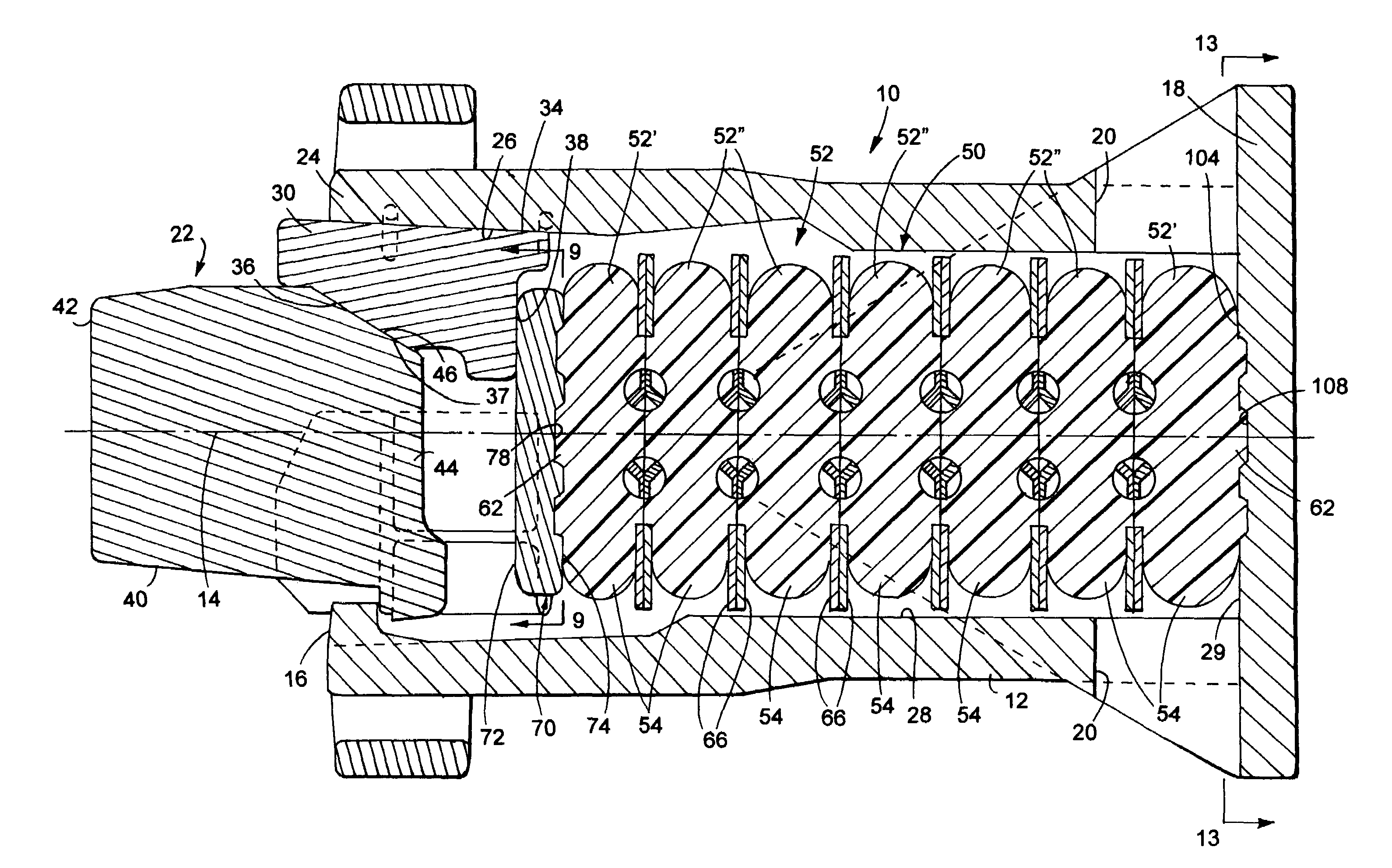
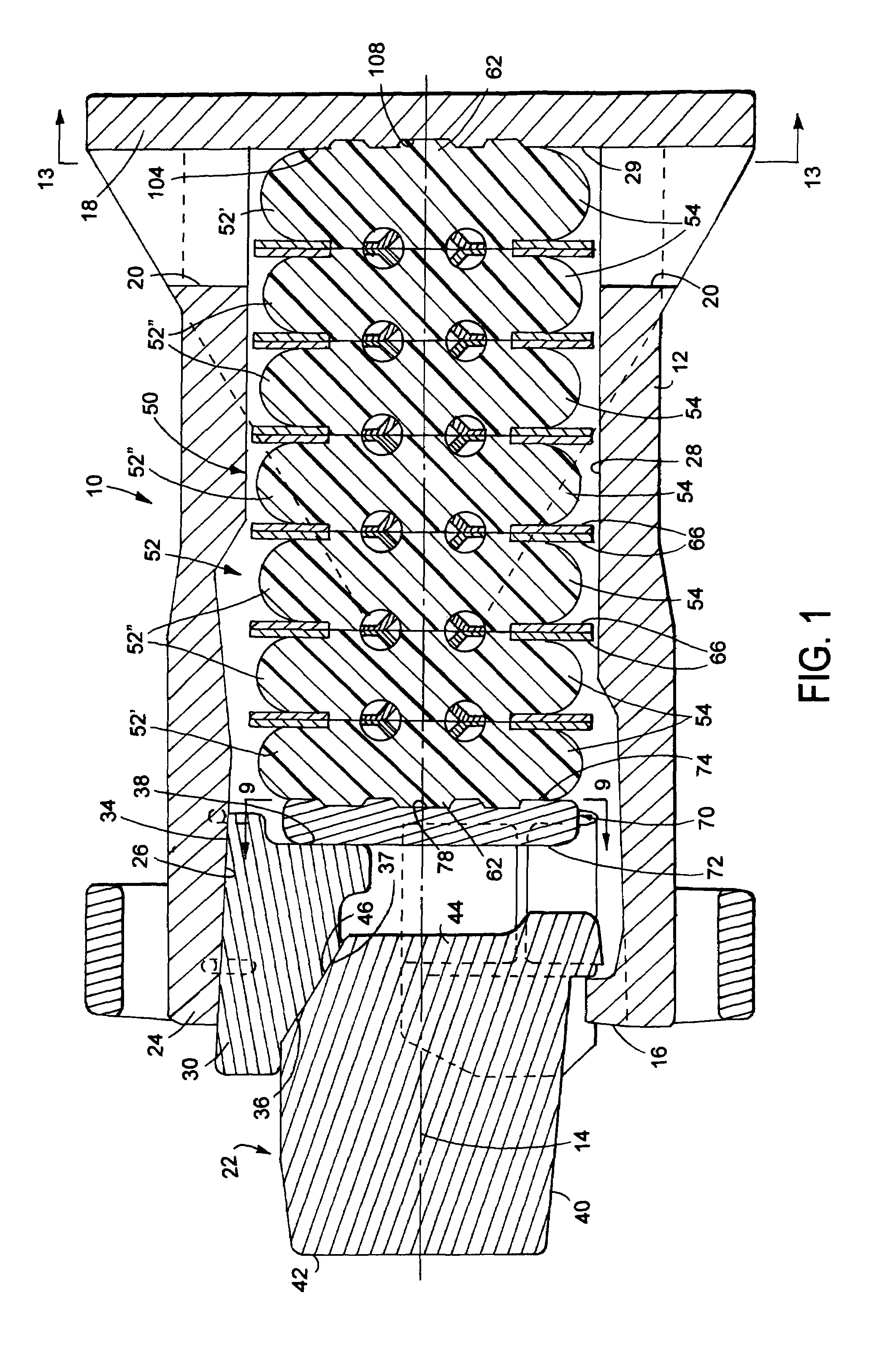
[0037]Referring now to the drawings, wherein like reference numeral indicate like parts throughout the several views, there is shown in FIG. 1. a railroad car draft gear, generally indicated by reference numeral 10, adapted to be carried within a yoke (not shown) arranged in operable combination within a centersill (not shown) of a railcar. The draft gear 10 includes an axially elongated hollow housing 12 defining a longitudinal axis or centerline 14 for the draft gear 10 and which is open at a first end 16 and closed toward a second end 18. Housing 12 is preferably cast and can include...


PUM


Abstract

A railroad car draft gear including a housing having an open end with a friction clutch assembly arranged in operable combination therewith. An elongated elastomeric spring assembly is disposed within the housing for storing energy during axial compression of the draft gear. A spring seat is arranged within the housing between the spring assembly and an end portion of each friction member forming part of the friction clutch assembly. The spring seat defines a surface, arranged in direct contacting relation with an end of the spring assembly, and defines at least one surface incongruity for limiting radial expansion with the elastomeric spring at the end of the spring assembly arranged in direct contacting relation with the spring seat along at least two axes when an axial load is applied to the draft gear.

Description

FIELD OF THE INVENTION[0001]The present disclosure generally relates to railroad cars and, more specifically, to a railroad car draft gear utilizing an elastomeric spring assembly for storing and dissipating energy during operation of the draft gear.BACKGROUND OF THE INVENTION[0002]Railroad car draft gears have been used for many years at opposite ends of a railcar to absorb and cushion impact forces. Most railcar draft gears include a cast housing having an inwardly tapered bore at an open end, a spring disposed within the housing, a series of metal friction shoes or members arranged in the tapered bore of the housing and movable against the spring upon compression of the draft gear, and a wedge disposed in operable combination with the friction members such that impact blows directed against the wedge are transferred axially to the spring and radially to the housing. In most railcar draft gears, a spring seat or follower is arranged between an end portion of each friction member a...

Claims


Application Information

Patent Timeline
Patent Type & Authority Patents(United States)
IPC IPC(8): B61G9/06
CPCB61G9/06F16F1/40F16F1/376
Inventor PALERMO, MICHAEL R.CARLSTEDT, RICHARD A.JURASEK, KRIS C.
Owner MINER ENTERPRISES INC
Why Eureka
Try Eureka