Continuous casting plant

a technology of continuous casting and casting machine, which is applied in the direction of continuous steel casting plant, etc., can solve the problems of affecting the flow ratio in the bath level region, and achieve the effects of increasing the stirring effect, constant electrical stirring power, and improving stirring power

Inactive Publication Date: 2009-12-15
CONCAST AG
View PDF10 Cites 1 Cited by
  • Summary
  • Abstract
  • Description
  • Claims
  • Application Information

AI Technical Summary

Benefits of technology

[0013]The object of the invention is to create a continuous steel casting plant for billet and bloom formats, preferably with a substantially rectangular slab cross-section, or one similar to rectangular, which achieves a combination of the following partial results. It should ensure on the one hand a high casting capacity with as small a number of slabs as possible, and thereby minimum investment and maintenance costs, and on the other hand an improved slab quality. The improvement in the slab quality should in particular prevent slab defects in the corner areas, such as cracks, solidification defects and casting powder inclusions in the slab shell, but also deviations in dimensions, such as rhomboidity, bulges and indents. The continuous casting plant according to the invention should furthermore reduce investment and maintenance costs for support guide stands and additionally improve the profitability and slab quality when permanent mold stirring devices are used.
[0014]With the continuous casting plant according to the invention it is possible to cast larger billet and bloom formats and preform slabs at higher casting speeds and without a support guide, or with a guide of reduced support width and / or support length, immediately below the permanent mold. At a preset production capacity the number of slabs can thereby be reduced and investment costs saved. At the same time the maintenance costs of the plant are reduced both because of the smaller number of slabs and because of the omission or reduction of support guides for the cast slabs. By enlarging the edge roundings of the cast slabs critical stresses in the remaining flat slab shell, produced by the ferrostatic pressure of the liquid core, can be considerably reduced when the slab emerges from the permanent mold. A shortening of the straight sections of the circumference of the die cavity located between the rounded-out corners by 10%, for example, reduces the flexural stress in these sections, likely to cause a bulge, by approximately 20%.
[0015]Besides these economic advantages, the slab quality is additionally improved in a great many respects. By controlling a selective elimination of the gap between the slab shell and the wall of the permanent mold or selective reshaping of the slab shell in the area of the fillet arc, the growth of the slab shell is evened out over the circumference of the slab and over predetermined parts of the length of the permanent mold, thereby improving the slab structure and preventing slab defects such as cracks, etc., in the edge areas. Additionally, geometric slab defects such as rhomboidity, bulges, etc., can be reduced or eliminated. However, enlargement of the rounded-out corners also influences the flow ratios in the region of the bath level. If casting powder is used to cover the bath level, with increasing enlargement of the rounded-out corners an evening-out of the conditions for the re-fusion of the casting powder can be achieved on the entire circumference of the meniscus. This advantage is further recognizable in permanent molds with stirring devices. Slab defects such as casting powder and slag inclusions, in particular in the edge areas, but also slab surface defects, can be reduced by evening-out the lubricating effect of the casting powder. Additional quality advantages are achievable by adapting the size of the rounded edges of the slab to the requirements of the subsequent rolling or forging operations.
[0024]Large rounded corners in the die cavity create advantages not only in casting with a casting powder covering of the bath level. With increasing size of the rounded corner it is also possible to increase the stirring effect in the bath level and in the liquid sump with constant electrical stirrer power. This possibility of improving the stirring power by the geometric shaping of the die cavity creates additional structural freedoms in installing stirrers in the billet and bloom permanent molds.

Problems solved by technology

However, enlargement of the rounded-out corners also influences the flow ratios in the region of the bath level.

Method used


Image

  • Continuous casting plant
  • Continuous casting plant
  • Continuous casting plant

Examples


Embodiment Construction

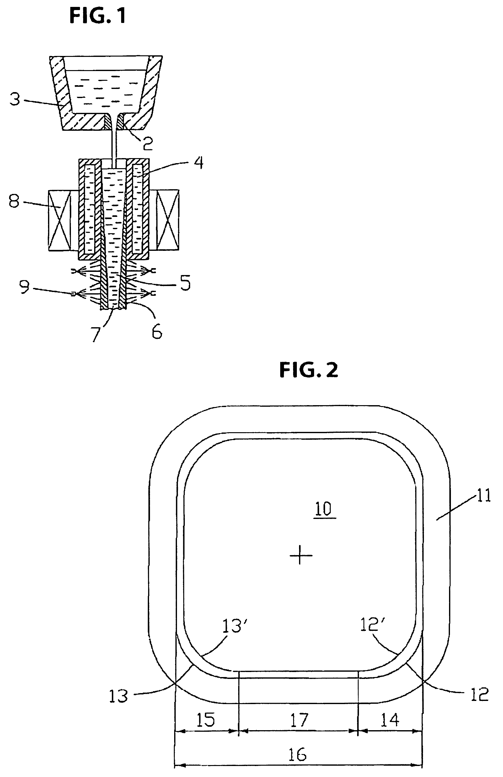
[0034]In FIG. 1 liquid steel flows vertically into a permanent mold 4 through a discharge nozzle 2 of an intermediate vessel 3. The permanent mold 4 has, for example, a rectangular die cavity for a billet cross-section of 120×120 mm2. A partially solidified slab is denoted by 5, a slab shell is denoted by 6 and a liquid core is denoted by 7. A height-adjustable electromagnetic stirring device 8 is illustrated schematically outside the permanent mold 4. It can also be arranged inside the permanent mold 4, for example in the water jacket. The stirring device 8 produces a horizontally circulating rotary movement in the region of the bath level and in the liquid sump. Immediately adjoining the permanent mold 4 is a first secondary cooling zone, without slab support and provided with spray nozzles 9.

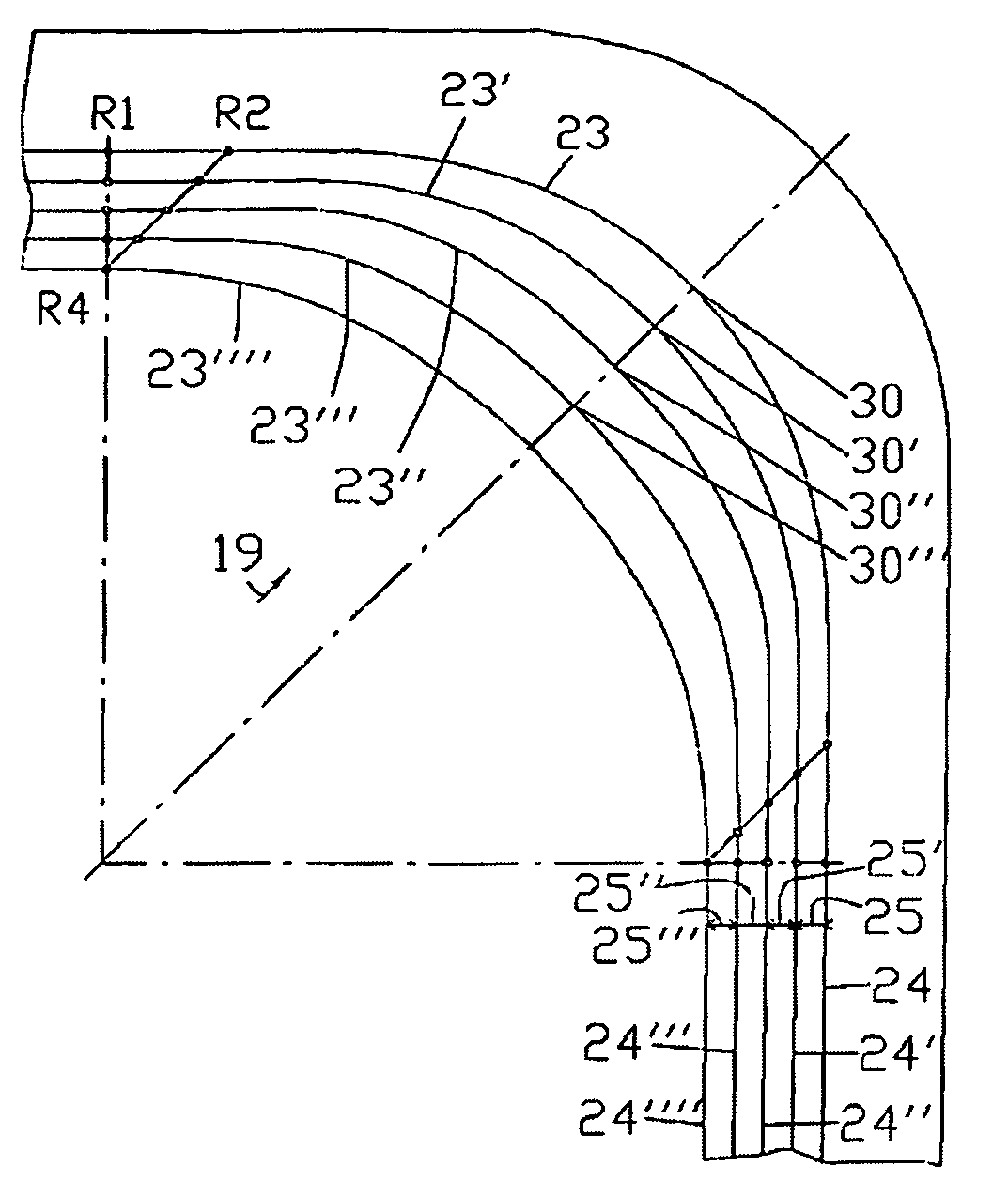
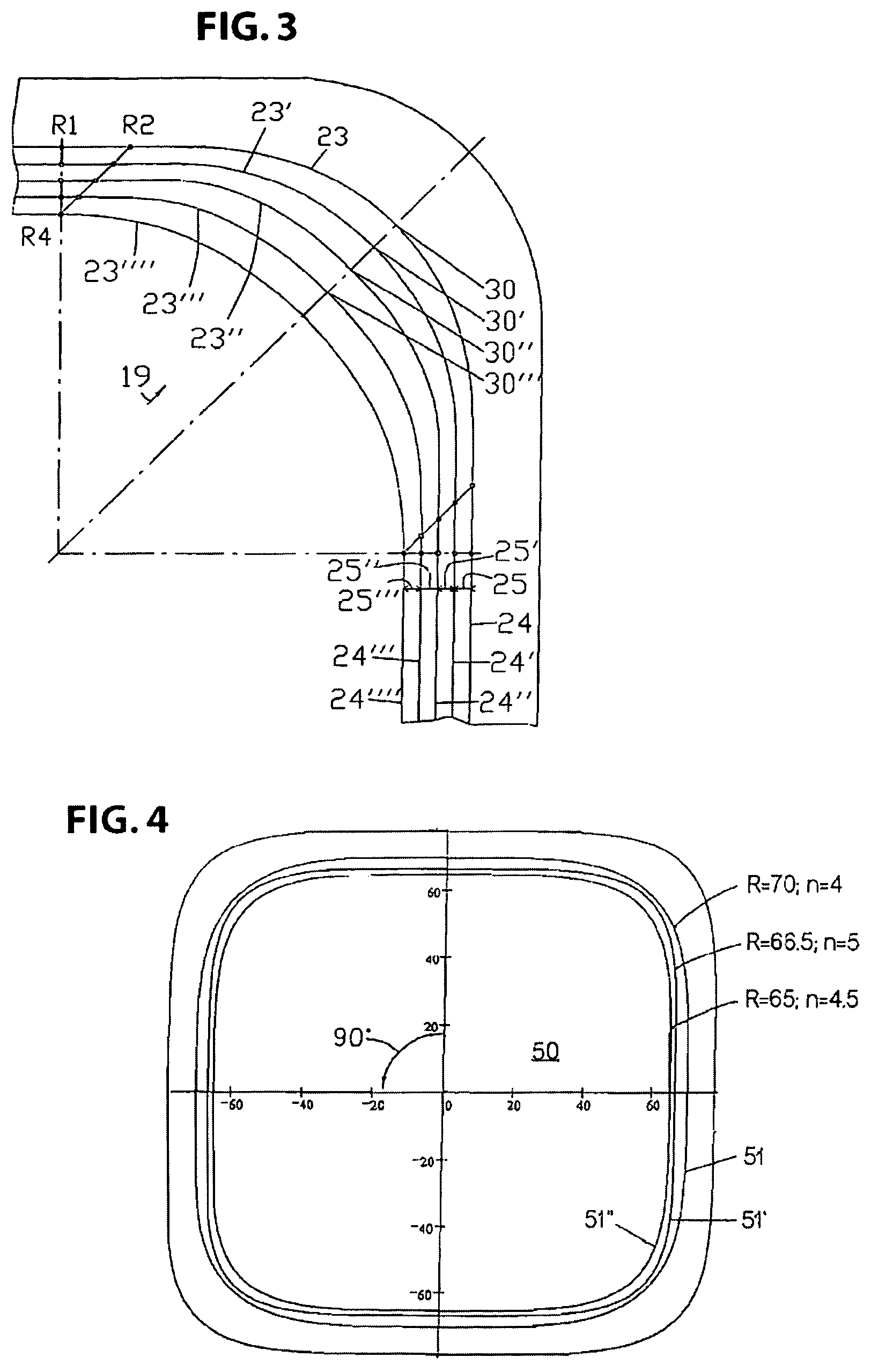
[0035]In FIG. 2 a die cavity, denoted by 10, of a permanent mold pipe 11 is provided with fillet arcs 12, 12′, 13, 13′ in the corner areas. The rounded-out portion 14, 15 of the fillet arcs 1...


PUM

PropertyMeasurementUnit
lengthaaaaaaaaaa
fillet radiiaaaaaaaaaa
lengthaaaaaaaaaa

Abstract

The invention relates to a continuous casting installation, for example for steel billet and bloom formats having substantially rectangular or circular cross-section. The invention improves the strand structure in the corner areas, to avoid rhomboidity, cracks and dimensional imperfections of the strand cross-section while achieving a high throughput capacity per strand and reducing investment and running costs. The fillets of the groove curvatures in the die cavity amount to a proportion of the length of the side of the strand cross-section. The degree of curvature 1 / R of the groove curvatures decreases in the direction of the strand at least along at least partial length of the entire casting die, thereby achieving gap elimination between the casting shell and the casting die wall and / or a targeted casting shell shaping in the area of the groove curvature. The continuous casting installation, directly downstream of the casting die, may thus be provided with a strand support-free secondary cooling zone or a supporting guide in the secondary cooling zone that is reduced in its supporting width and / or supporting length.

Description

[0001]This application is a continuation of PCT Application No. PCT / EP2005 / 013078, filed Dec. 7, 2005, which claims the benefit of European Application No. 04030926.2 filed Dec. 29, 2004, the entirety of which are incorporated by reference herein.BACKGROUND OF THE INVENTION[0002]1. Field of the Invention[0003]The invention relates to a continuous steel casting plant for billet and bloom formats.[0004]2. Description of Related Art[0005]Long continuous casting products are cast predominantly in tubular permanent molds with a rectangular, and often with an approximately square or round, cross-section. The billet and bloom slabs are then further processed by rolling or forging.[0006]For producing continuous casting products with good surface and texture quality, in particular billet and bloom slabs, a uniform heat transition along the circumferential line of the slab cross-section between the slab being formed and the wall of the die cavity is of crucial importance. Many proposals are k...

Claims


Application Information

Patent Timeline
Patent Type & Authority Patents(United States)
IPC IPC(8): B22D11/04
CPCB22D11/128B22D11/041
Inventor ROEHRIG, ADALBERTKAWA, FRANZ
Owner CONCAST AG
Why Eureka
Try Eureka