

Fireproof shutter that opens and closes without power
- Summary
- Abstract
- Description
- Claims
- Application Information
AI Technical Summary
Benefits of technology
Problems solved by technology
Method used
Image

Examples
first embodiment
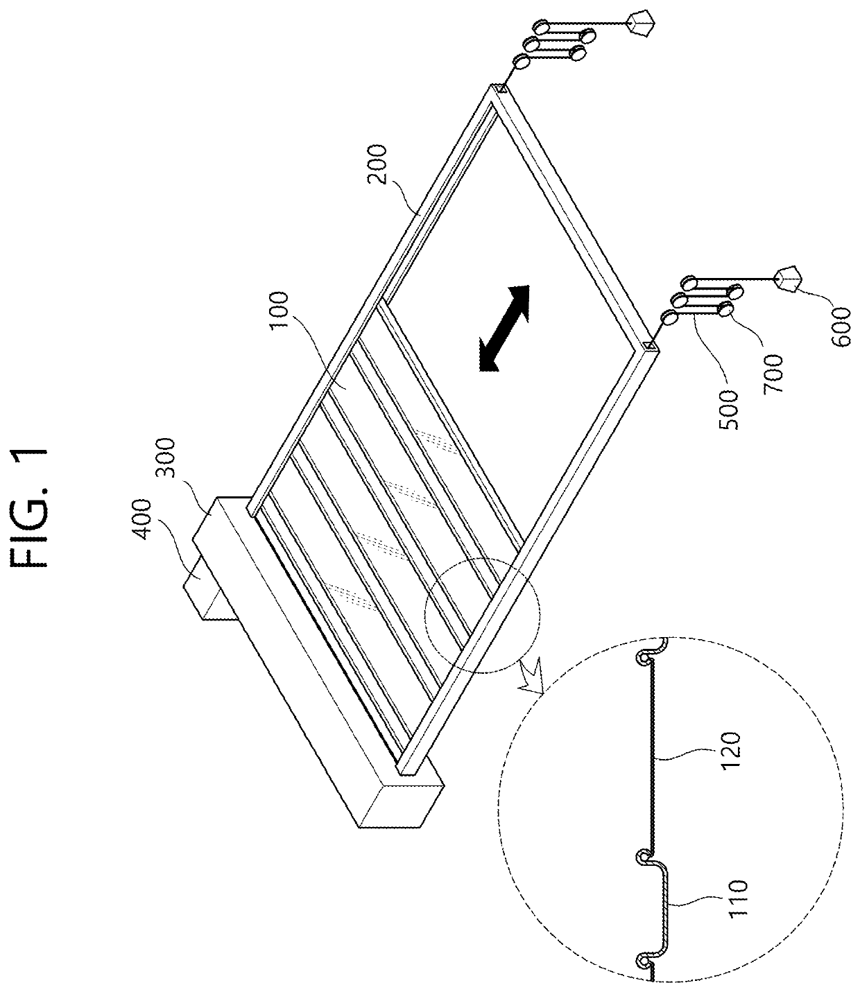
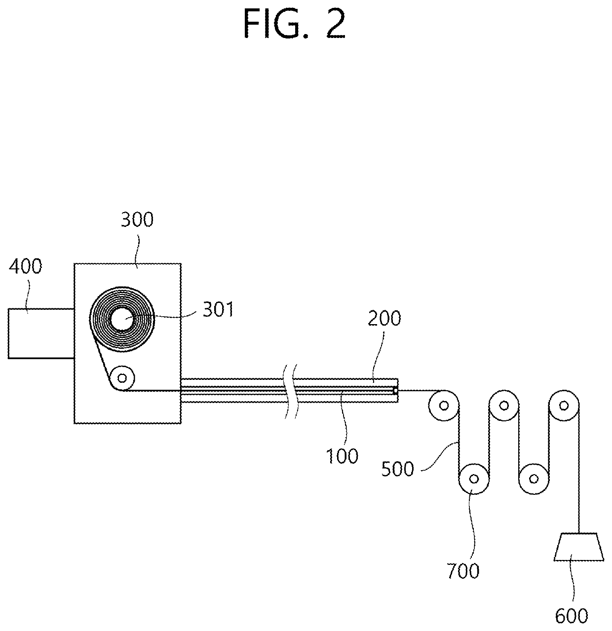
[0024]FIG. 1 is a perspective view schematically illustrating a fireproof shutter according to a first embodiment of the present disclosure, and FIG. 2 is a cross-section view illustrating the fireproof shutter according to the first embodiment of the present disclosure.
[0025]Referring to FIGS. 1 and 2, the fireproof shutter according to the first embodiment of the present disclosure may be configured to penetrate a courtyard of a building so as to block flames and smoke.
[0026]The fireproof shutter according to the first embodiment of the present disclosure may include a shutter 100, a shutter track 200, a coil box 300, a winding motor 400, a traction wire 500, a weight 600, and a pulley 700.
[0027]The shutter 100 may be formed of a material capable of satisfying fireproof and flameproof conditions. For example, the material of the shutter 100 may include a steel shutter and / or a fireproof screen made of silica fibers. The fireproof shutter according to the first embodiment of the pr...
second embodiment
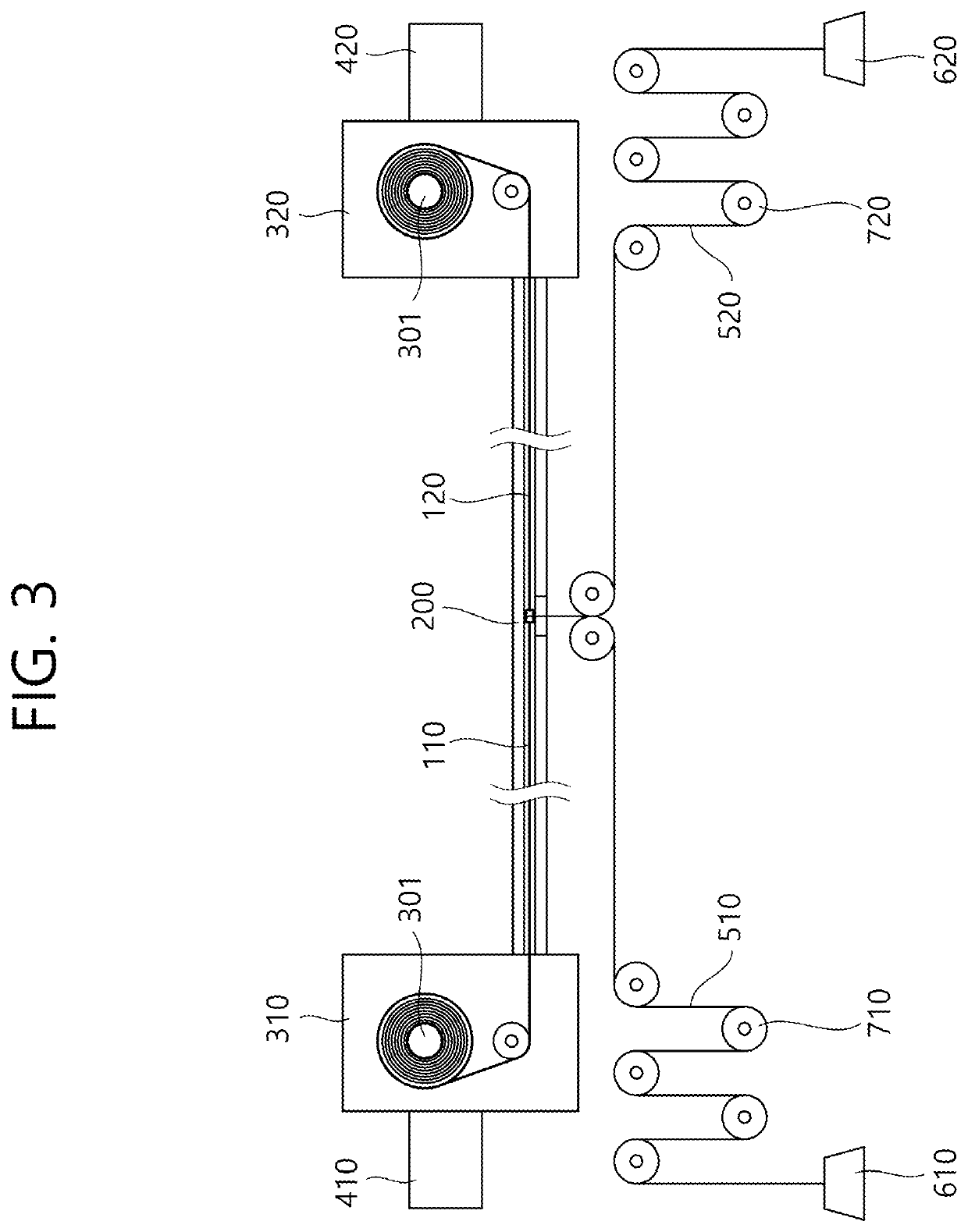
[0035]FIG. 3 is a cross-section view illustrating a fireproof shutter according to a second embodiment of the present disclosure.
[0036]Referring to FIG. 3, in the fireproof shutter according to the second embodiment of the present disclosure, the shutters 100 may be provided in a pair so that the shutters 100 can be respectively deployed in directions opposite to each other. The shutter 100 may be provided in a form separated into a first shutter 110 and a second shutter 120. According to this, the coil box 300, the winding motor 400, the traction wire 500, and the pulley 700 may be provided as a pair, respectively.
[0037]That is, the first shutter 110 is disposed to be deployed in a right direction of FIG. 3, and the second shutter 120 is disposed to be deployed in a left direction of FIG. 3. A first coil box 310 and a first winding motor 410 are disposed on a left side of the first shutter 110, and a first traction wire 510 is connected to a right end of the first shutter 110. A se...
third embodiment and fourth embodiment
[0040]FIG. 4 is a cross-section view illustrating a fireproof shutter according to a third embodiment of the present disclosure, and FIG. 5 is a cross-section view illustrating a fireproof shutter according to a fourth embodiment of the present disclosure.
[0041]Referring to FIGS. 4 and 5, in the fireproof shutter according to the third embodiment of the present disclosure, the shutter 100 may close a fire zone in horizontal and vertical directions.
[0042]That is, a shutter track 200 may include a first shutter track 210 which is disposed in the horizontal direction, a second shutter track 220 which is curved from the first shutter track 210, and a third shutter track 230 which extends in the vertical direction from the second shutter track 220.
[0043]As described above, in the fireproof shutter according to the third embodiment, the shutter 100 can be deployed to extend in the horizontal and vertical directions, and thus, it is possible to effectively prevent flame from spreading in t...
PUM
 Abstract
Description
Claims
Application Information