
Image capturing device using correction information for preventing at least a part of correction process from being performed when image data is corrected at an external device

a technology of image data and capturing device, which is applied in the field of image capturing device using correction information, can solve the problems of increasing user load, requiring troublesome operations for inputting finish information, scene information, etc., and not being able to prevent an image from being made, so as to eliminate the user load of making the settings of an image forming instruction

Active Publication Date: 2009-12-15
OM DIGITAL SOLUTIONS CORP
View PDF23 Cites 13 Cited by
  • Summary
  • Abstract
  • Description
  • Claims
  • Application Information

AI Technical Summary

Benefits of technology

[0025]The present invention was developed to overcome the above described problems. A first object of the present invention is to accurately reflect the shooting intention of a user when a visible image is formed, without imposing a load on the user. A second object of the present invention is to eliminate the user load of making the settings of an image forming instruction, such as printing, display, etc. of a shot image, when a visible image is formed. A third object of the present invention is to reduce a user load of making the settings of an electronic camera without restricting the original role of a recording medium.

Problems solved by technology

With these techniques, however, finish information, scene information, etc. must be input at the time of each shooting or printing, leading to an increase in a user load.
As a result, troublesome operations for inputting finish information, scene information, etc. are required from the shooting to the printing.
However, this proposed technique is not intended to prevent an image that does not conform to the shooting intention of a user from being printed at the time of printing.
Therefore, even if a user attempts to print an image that he or she shoots by changing shooting conditions, etc. so as to intentionally make the image nonstandard, the shooting intention of the user cannot be accurately reflected.
However, a user must make troublesome settings such as a printing mode setting, an image process setting, etc. for an image forming instruction, which leads to an increase in a user load.
Additionally, the amount of program data, which is stored on a recording medium in order to implement a predetermined function, becomes large with an increase in the number of functions, and occupies more of the space of the recording medium, and can possibly restrict the original role of recording image data.
However, if the number of settings becomes large due to the equipment of such a function, a user can make fine settings, but a heavier load of making the settings is imposed on the user, and the operability of an electronic camera is degraded.

Method used


Image

  • Image capturing device using correction information for preventing at least a part of correction process from being performed when image data is corrected at an external device
  • Image capturing device using correction information for preventing at least a part of correction process from being performed when image data is corrected at an external device
  • Image capturing device using correction information for preventing at least a part of correction process from being performed when image data is corrected at an external device

Examples


Embodiment Construction

[0074]Hereinafter, preferred embodiments according to the present invention are described with reference to the drawings.

[0075]First of all, the first preferred embodiment of the present invention is described.

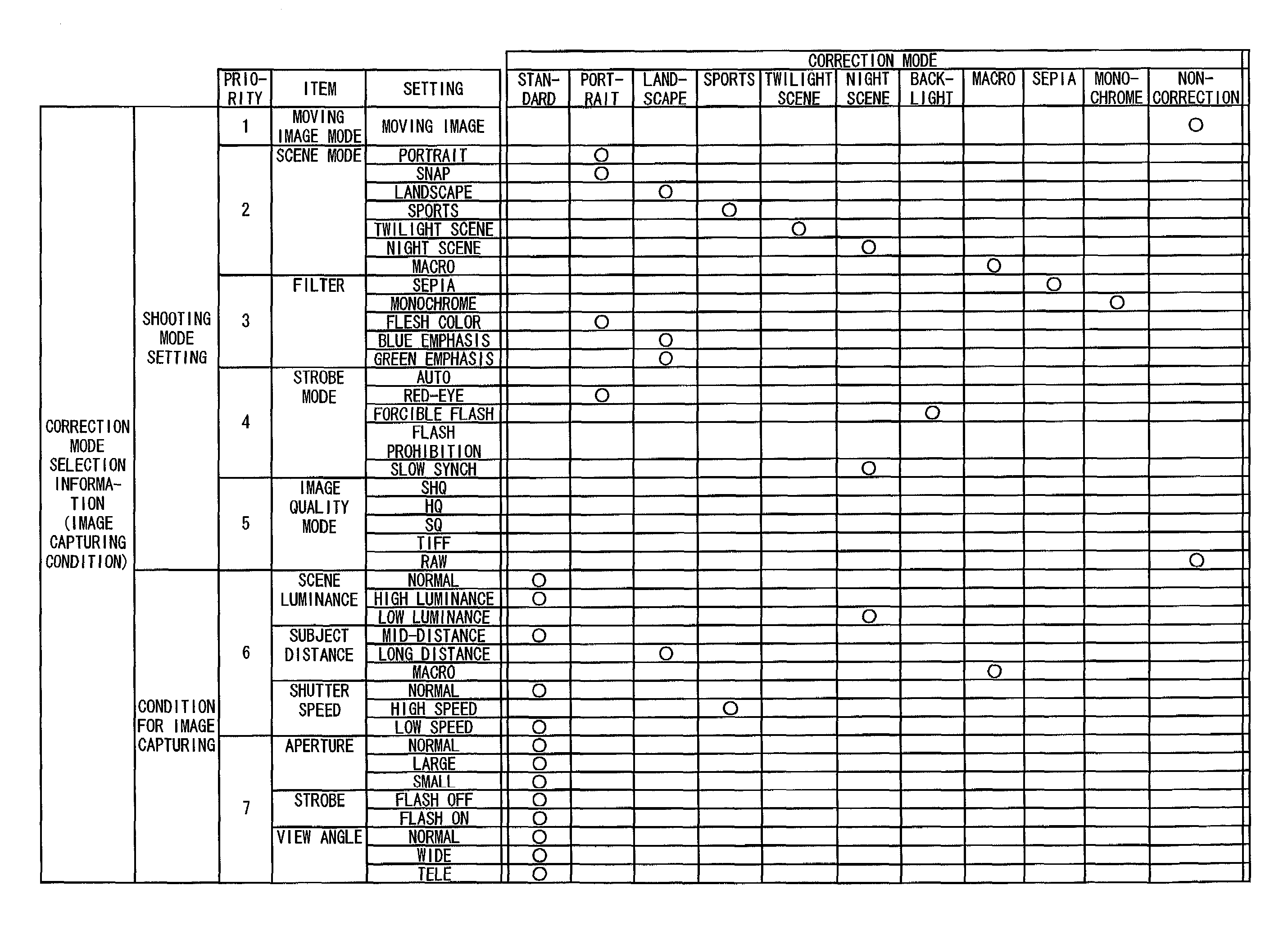
[0076]Note that a shooting mode and a condition for image capturing indicate an image capturing condition, a correction mode indicates image forming instruction information or an image forming instruction mode, a camera mode indicates a shooting condition for exposure or image quality, and a correction condition indicates correction instruction information, in the first preferred embodiment.

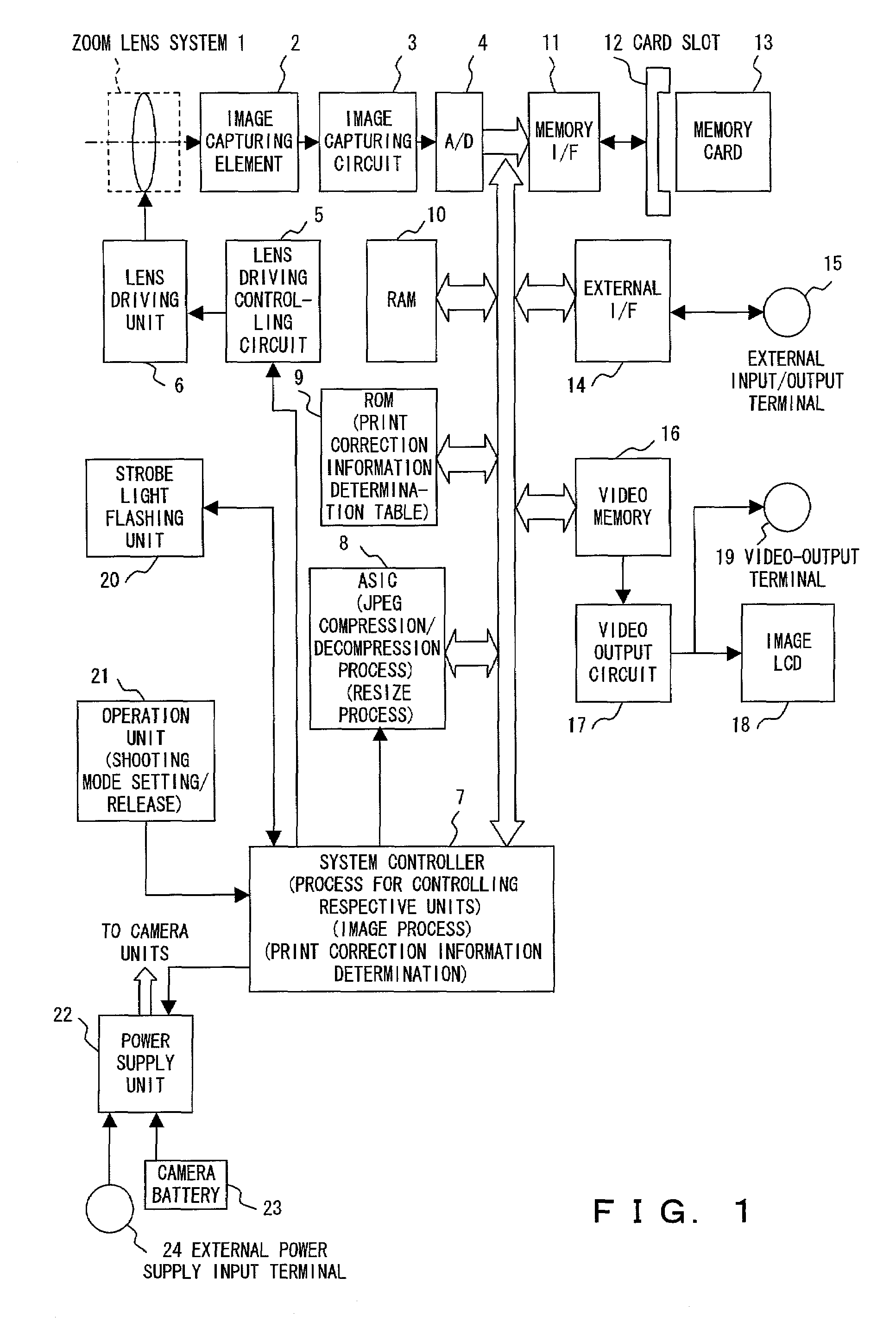
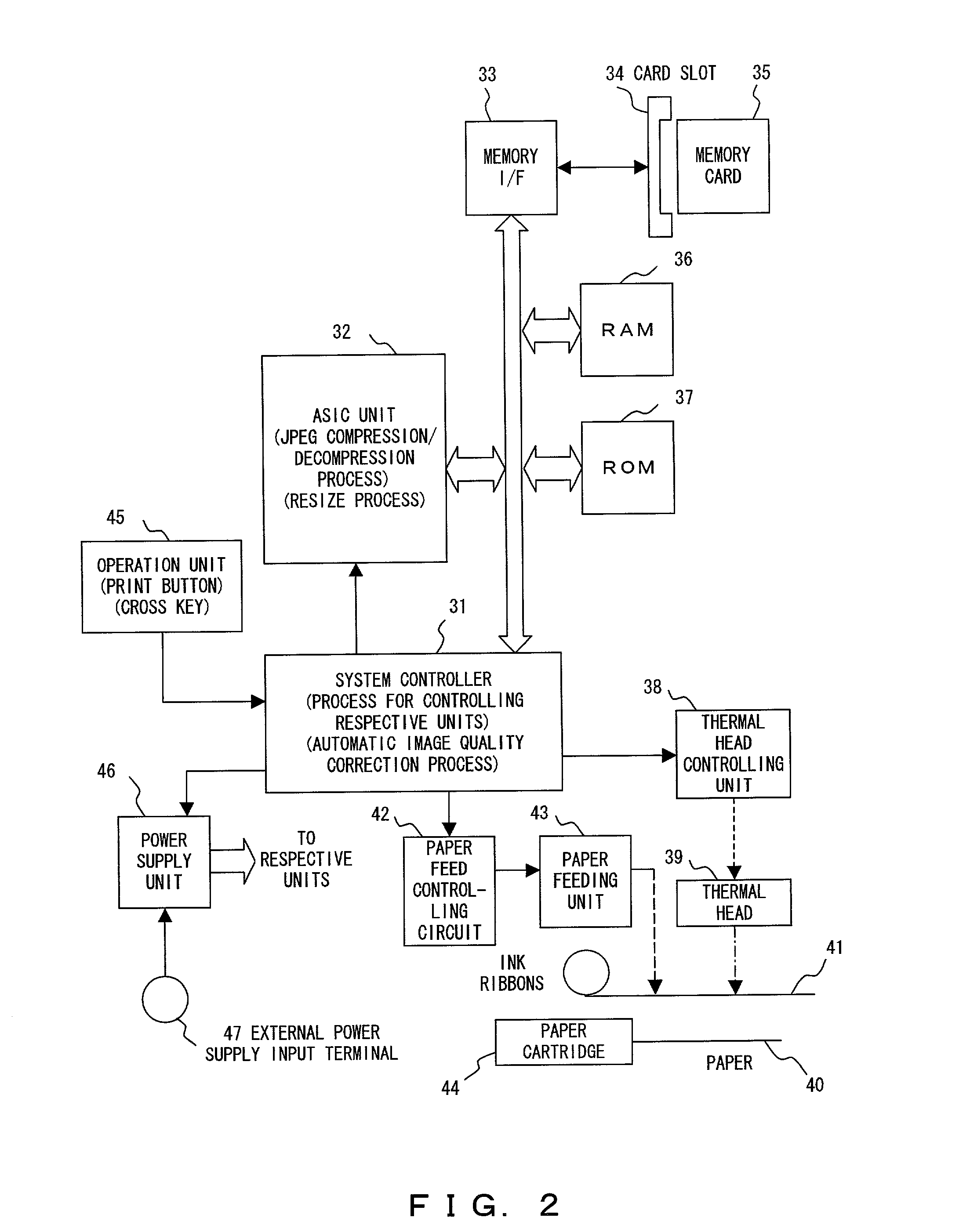
[0077]FIG. 1 is a block diagram showing the configuration of an electronic camera included in an electronic camera system according to the first preferred embodiment. The electronic camera shown in this figure comprises a function for enabling shooting based on a shooting mode or a camera mode, which is set by a user (a person who shoots an image). FIG. 2 is a block diagram showing the conf...


PUM


Abstract

When shooting is made, an electronic camera selects a correction mode and a correction condition, which reflect the shooting intention of a user with the highest accuracy when a visible image is formed, based on a set shooting mode, a condition for image capturing at the time of shooting, and a camera mode. The electronic camera then associating the correction mode and the correction condition with the image data obtained by shooting, and records the mode and the condition in association with the image data on a memory card. When a printer prints an image based on the image data, it performs a process for a correction when a visible image is formed, based on the correction mode and the correction condition, which are associated with the image data.

Description

BACKGROUND OF THE INVENTION[0001]1. Field of the Invention[0002]The present invention relates to a technique applied to an electronic camera, an image forming apparatus, a storage medium, an electronic camera system, etc.[0003]2. Description of the Related Art[0004]In recent years, there has been a growth in the number of cases where an image is appreciated by making a printer (image forming apparatus) print the image shot with an electronic camera, or by making a display of a TV (television), a PC (Personal Computer), etc. show the image.[0005]On the basis of such a background, for example, a printer is equipped with various functions to print a more suitable image. The functions include an automatic correction function. This is a function for analyzing image data to be printed, and for performing an image process for a correction based on a result of the analysis. Normally, the image process for a correction is performed to satisfy a uniform condition (standard image condition) th...

Claims


Application Information

Patent Timeline
Patent Type & Authority Patents(United States)
IPC IPC(8): H04N5/225H04N1/21
CPCH04N1/2158H04N1/32128H04N2101/00H04N2201/3277H04N2201/3243H04N2201/3252H04N2201/3242
Inventor TOYODA, TETSUYAHIGUCHI, MASAYU
Owner OM DIGITAL SOLUTIONS CORP
Learn More