
Continuous casting apparatus, continuous casting method and aluminum alloy cast bar

a casting apparatus and continuous casting technology, applied in the field of continuous casting apparatus, continuous casting method and aluminum alloy casting bar, can solve the problems of large casting defect, ingot tearing, unevenness between high and low portions of the mold, etc., and achieve stable casting, reduce the amount of lubricant, and perform stably and smoothly

Active Publication Date: 2009-12-29
RESONAC CORPORATION
View PDF14 Cites 0 Cited by
  • Summary
  • Abstract
  • Description
  • Claims
  • Application Information

AI Technical Summary

Benefits of technology

[0044]According to the first, second, twentieth and twenty-first aspects of the invention, the insulation member is provided with the separation layer. Therefore, since the separation layer blocks the lubricant which has been supplied into the mold and transferred to the insulation member, it prevents the lubricant from reacting with the molten alloy and from entering the molten metal-receiving portion. This suppresses consumption of the lubricant, resulting in reduction in the amount of the lubricant. Thus, high-speed casting can be performed stably and smoothly with a reduced amount of the lubricant. In addition, there are not produced lubricant reaction products which would otherwise be produced on the wall surface of the insulation member or in the vicinity thereof, resulting in considerable reduction in ingot failure rate.
[0052]According to the sixteenth and seventeenth aspects of the invention, since the first and second aspects of the invention are applied in casting of aluminum alloy having a magnesium content of 0.5 mass % or more, while conventionally, such a magnesium-containing aluminum alloy has been difficult to cast stably without using a larger amount of the lubricant, effects similar to those described above in relation to high-speed casting can be exhibited, including reduction in the amount of the lubricant, prevention of occurrence of lubricant reaction products, stable and smooth casting, and prevention of occurrence of ingot failure.

Problems solved by technology

These phenomena create unevenness between high and low portions of the mold in terms of the lubrication state between the mold inner wall and the molten metal or the solidifying shell of a cast ingot.
For example, in a lower portion of the mold, since no lubricant is present between the mold inner wall and the molten metal or the solidifying shell, the molten metal seizes on the mold's inner wall, breaking the solidifying shell to allow the not-yet-solidified molten metal to outflow, producing a large casting defect, or in an extreme case, tearing off the ingot and preventing continuation of the casting operation.
Meanwhile, at an upper portion of the mold inner wall, since lubricant is present in an excessive amount, which prevents close contact between the molten metal and the mold inner wall, the molten metal cannot be sufficiently cooled by the mold, permitting blowing out of unsolidified molten metal from the upper portion of the cast ingot.
If a large amount of lubricant is supplied, however, an excessive amount of gas may be produced to cause breakout, or when an excessive amount of lubricant contacts molten metal, lubricant reaction products will be produced.
These incidents are unfavorable, as they results in production of defective cast ingots.

Method used


Image

  • Continuous casting apparatus, continuous casting method and aluminum alloy cast bar
  • Continuous casting apparatus, continuous casting method and aluminum alloy cast bar
  • Continuous casting apparatus, continuous casting method and aluminum alloy cast bar

Examples


first embodiment

[0066]Next the present invention will be described with reference to FIGS. 1 to 5.

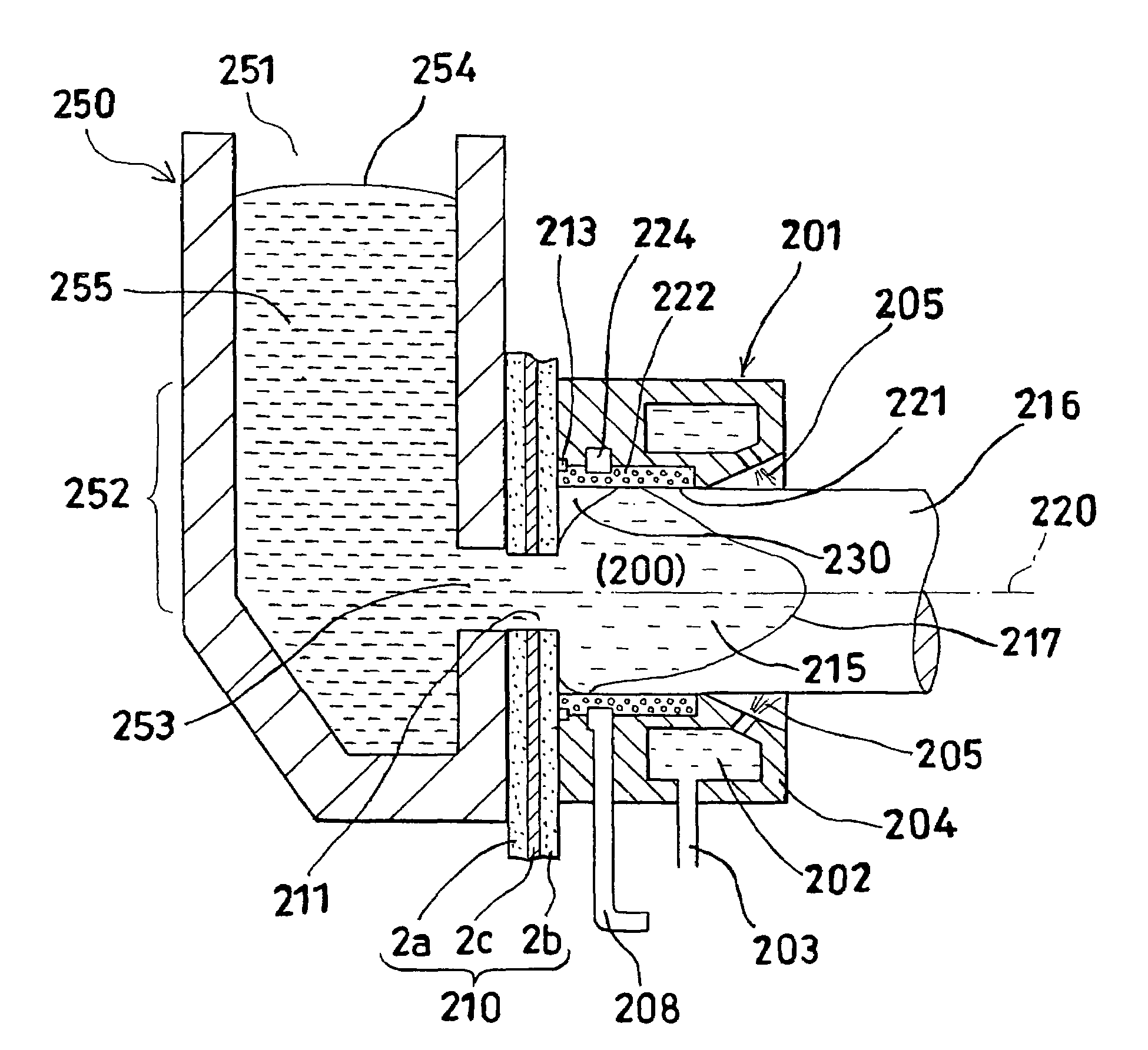
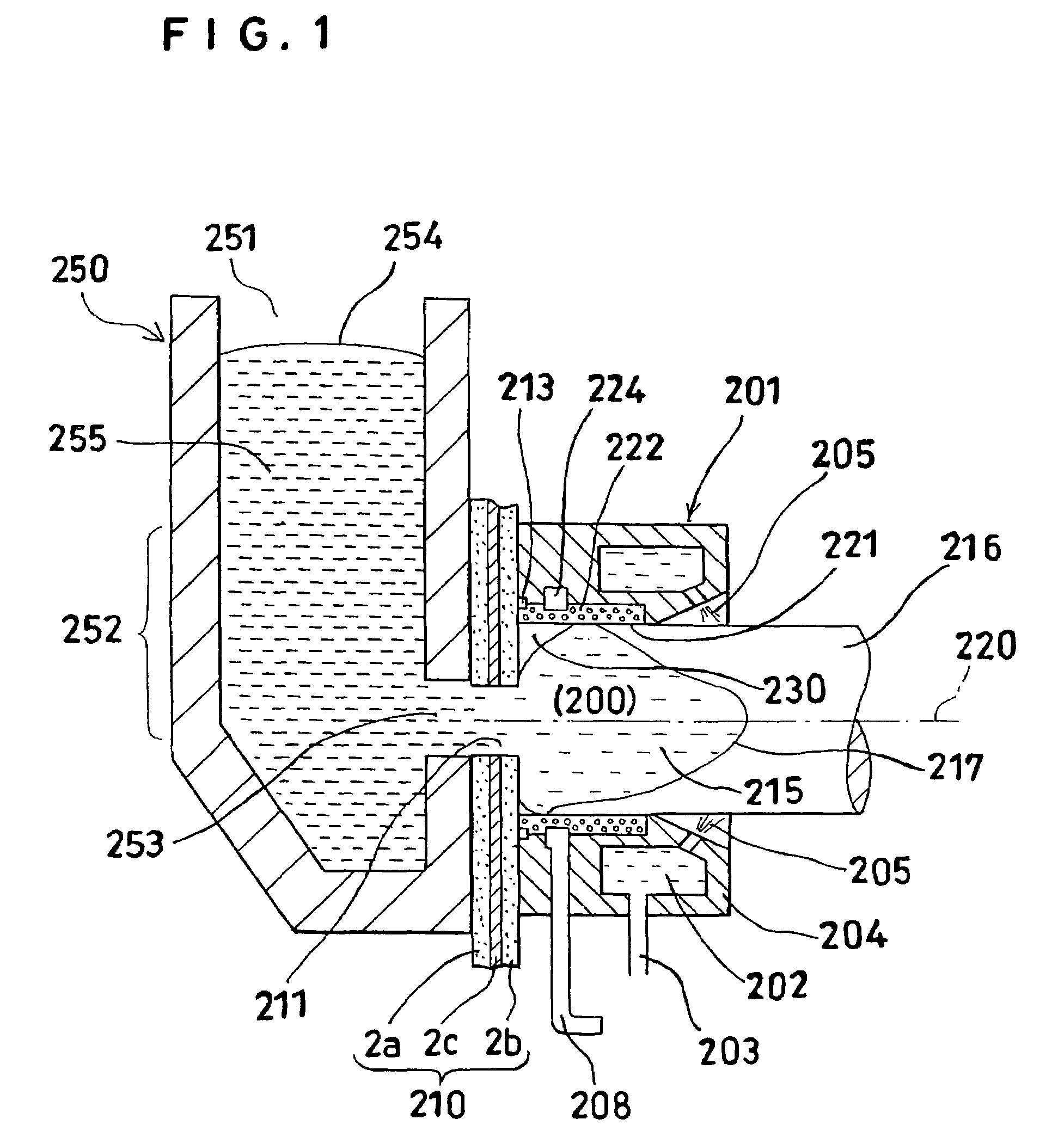
[0067]FIG. 1 shows the vicinity of a mold of the horizontal continuous casting apparatus of the present invention. In FIG. 1, the molten metal-receiving portion is a tundish 250. The tundish 250, a refractory plate 210 and a cylindrical mold (hereinafter referred to simply as “mold”) 201 are located such that molten alloy 255 stored in the tundish 250 is supplied via the refractory plate 210 to the mold 201. As described later in detail, the refractory plate 210 comprises a first insulation member 2a, a second insulation member 2b and a separation layer 2c. The mold 201 is supported such that the mold center axis 220 becomes approximately horizontal. In order to solidify the molten alloy 255 to form a solidified ingot 216, the mold 201 is provided therein with forced cooling means for cooling the mold 201 and at the exit thereof with forced cooling means for cooling the solidified ingot 216. In FIG. 1,...

second embodiment

[0113]Next, the present invention will be described with reference to FIG. 6, FIG. 7 and FIG. 8.

[0114]FIG. 6 shows the vicinity of a mold of the horizontal continuous casting apparatus according to the second embodiment. FIG. 7 and FIG. 8 show the configurations of lubricant supply portions in the second embodiment. The difference between the first embodiment and the second embodiment resides in the configuration of the lubricant supply portion. In addition, the refractory plate 210 includes no separation layer and is configured only with an insulation member formed of, for example, Lumiboard.

[0115]In the second embodiment, as shown in FIG. 6 and FIG. 7(a), a lubricant supply conduit 224a is provided in the inner wall of the mold at a position proximal to the upstream end of the mold 201 and extended toward the downstream end of the mold 201. The width of the conduit 224a as measured in the horizontal direction is, for example, 2 to 13 mm (preferably, 2 to 7 mm.

[0116]Since the lubri...

third embodiment

[0131]Next the present invention will be described with reference to FIG. 9.

[0132]FIG. 9 is a diagram illustrating the position of the molten metal passage in the third embodiment. The third embodiment differs from the first embodiment in that the position of the molten metal passage 211 (molten metal supply port) is defined specifically. In addition, the refractory plate 210 includes no separation layer and is configured only with an insulation member formed of, for example, Lumiboard.

[0133]As shown in FIG. 9, in the third embodiment, the relationship between the molten metal passage 211 and the mold 201 is defined such that the lowermost position P1 of the inner wall of the molten metal passage is located at a position higher by the height h than the lowermost position P0 of the inner wall of the mold, the height h being equal to or larger than 8% (preferably, equal to or larger than 10%) of the inner diameter d of the mold.

[0134]Though the upper limit of the definition of the hei...


PUM

PropertyMeasurementUnit
thermal conductivityaaaaaaaaaa
diameteraaaaaaaaaa
mold lengthaaaaaaaaaa

Abstract

A continuous casting apparatus, continuous casting method and aluminum alloy cast bar enable stable and smooth high-speed casting with a reduced amount of a lubricant and prevent occurrence of breakout and lubricant reaction products, resulting in reduction in ingot failure. The present invention provides a continuous casting apparatus for producing aluminum alloy cast bars, including a tundish containing molten aluminum alloy, a mold which has an upstream end and a downstream end and to which the molten aluminum alloy is supplied through the upstream end of the mold, an insulation member which is disposed between the tundish and the upstream end of the mold and which has a molten metal passage for allowing communication between the tundish and the mold, and a separation layer disposed on the insulation member and having an aperture which is in communication with the molten metal passage, wherein a lubricant which has been supplied to the mold and transferred to the insulation members is blocked with the separation layer.

Description

CROSS REFERENCE TO RELATED APPLICATIONS[0001]This application is an application filed under 35 U.S.C. §111(a) claiming the benefit pursuant to 35 U.S.C. §119(e)(1) of the filing dates of Provisional Applications No. 60 / 623,339 filed Nov. 1, 2004 and Japanese Applications No. 2004-309251 filed Oct. 25, 2004 pursuant to 35 U.S.C §111(b).BACKGROUND OF THE INVENTION[0002]1. Field of the Invention[0003]The present invention relates to a continuous casting apparatus and continuous casting method for producing aluminum alloy cast bars by supplying molten alloy from a molten metal-receiving portion to a mold through a melt passage which penetrates insulation members provided between the molten metal-receiving portion and the mold; and to aluminum alloy cast bars.[0004]2. Description of the Prior Art[0005]In recent transportation equipment, due to desirability of reducing weight, aluminum alloy parts have come to be employed more frequently. Aluminum alloy parts for such purposes are produce...

Claims


Application Information

Patent Timeline
Patent Type & Authority Patents(United States)
IPC IPC(8): B22D11/045B22D11/07
CPCB22D11/003B22D11/045B22D11/07B22D11/049B22D11/0475C22C21/02C22C21/08C22C21/10C22C21/14C22C21/16C22C21/18B22D11/00B22D11/04
Inventor FUKUDA, MASASHIFUKUSHIMA, MASATOSHI
Owner RESONAC CORPORATION
Learn More