LED lamp with a heat sink

Inactive Publication Date: 2009-12-29
FU ZHUN PRECISION IND SHENZHEN +1
View PDF6 Cites 86 Cited by
  • Summary
  • Abstract
  • Description
  • Claims
  • Application Information

AI Technical Summary

Problems solved by technology

This issue has become a challenge for engineers to design the LED illumination, i.e. the LED lamp.

Method used


Image

  • LED lamp with a heat sink
  • LED lamp with a heat sink
  • LED lamp with a heat sink

Examples


Embodiment Construction

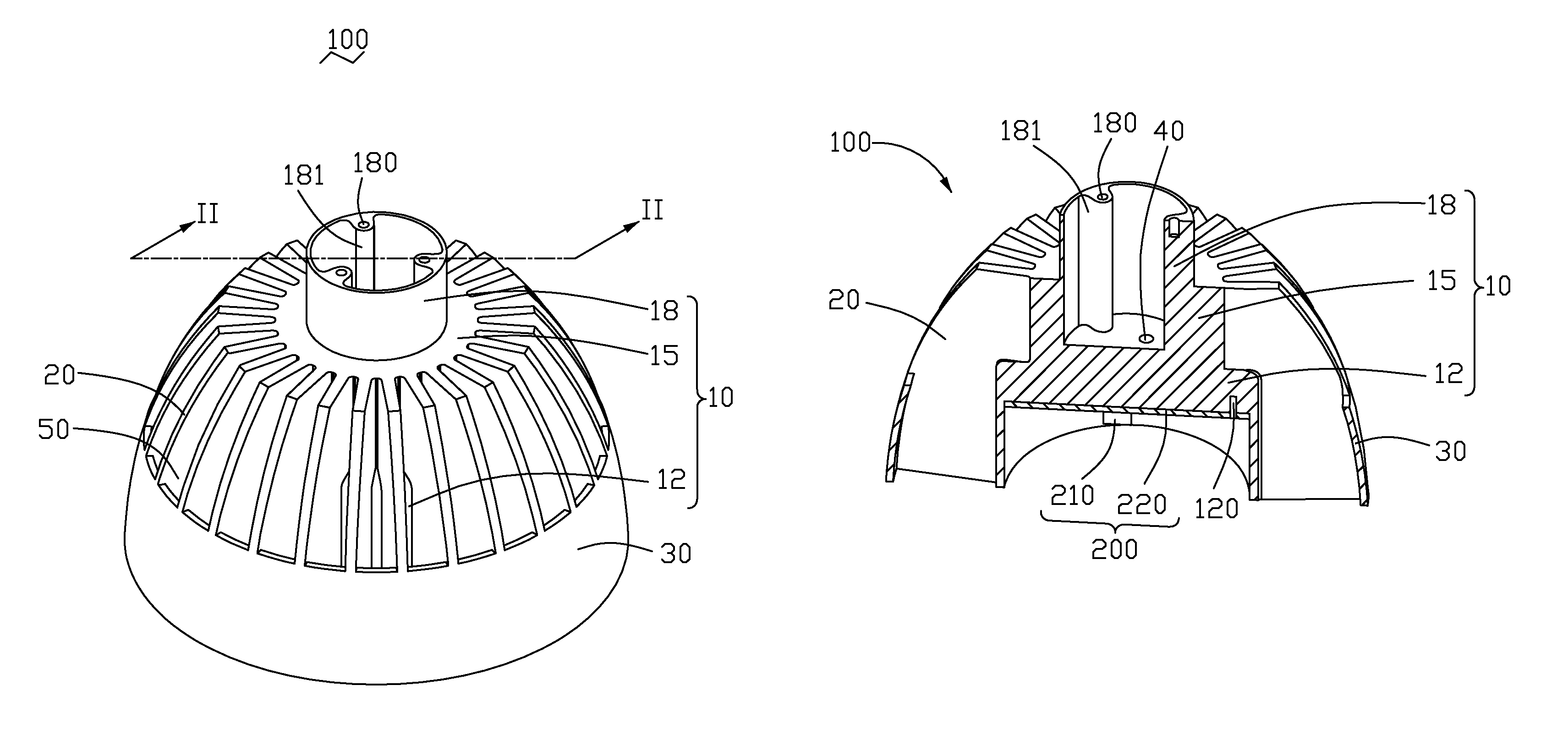
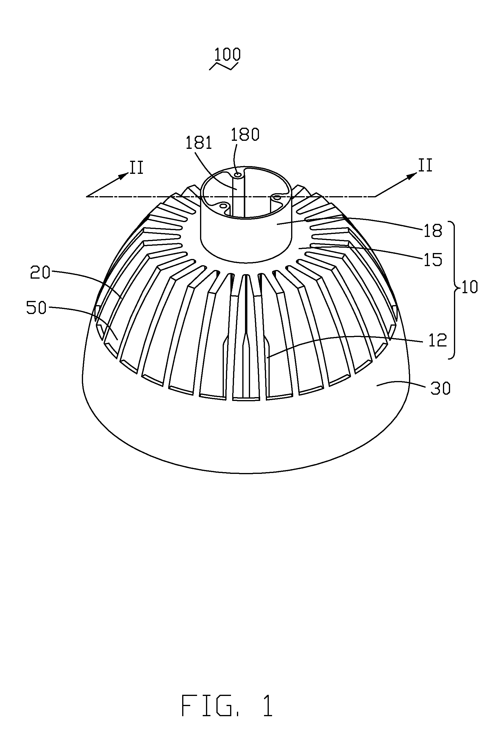
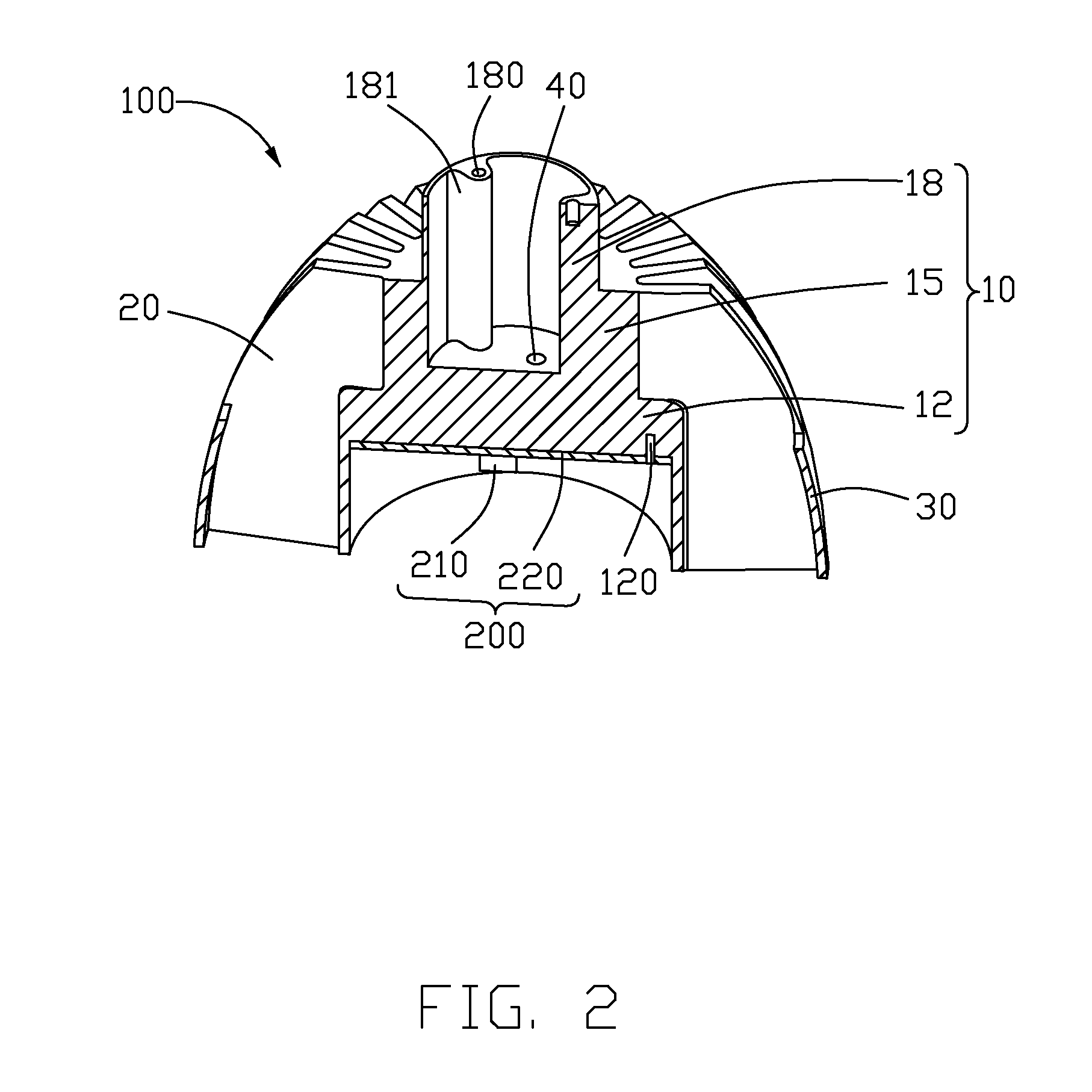
[0014]Referring to FIGS. 1-2, an LED (light emitting diode) lamp (not labeled) of a preferred embodiment of the invention comprises an LED module 200, a heat sink 100 for supporting and cooling the LED module 200.

[0015]The heat sink 100 comprises a heat conducting body 10 receiving the LED module 200 therein, a plurality of radial partition fins 20 extending from an outer surface of the body 10, and a curved wall 30 surrounding lower portions of the fins 20. The wall 30 has a configuration like a hollow frustum.

[0016]The body 10 comprises an absorbing portion 12, a transferring portion 15 extending upwardly from an upper portion of the absorbing portion 12, and a mounting portion 18 extending upwardly from an upper portion of the transferring portion 15. The absorbing portion 12 and the transferring portion 15 each have a cylindrical configuration and have a common axis. A diameter of the transferring portion 15 is smaller than that of the absorbing portion 12, and a diameter of the...


PUM


Abstract

An LED lamp includes a heat sink and an LED module. The heat sink includes a body, a plurality of radial partition fins extending evenly from an outer periphery of the body and a curved wall surrounding lower portions of the fins. The fins, the outer periphery of the body and the wall together define a plurality of channels each having a lower opening and a top opening. The LED module includes a plurality of LEDs and is received in the absorbing portion of the body. The LED module is supported by the absorbing portion of the body of the heat sink. Heat generated by the LEDs is transferred to the fins via the body. From the fins, the heat is dissipated to air. The channels each function as a chimney for accelerating heated air to flow upwardly through the fins.

Description

BACKGROUND OF THE INVENTION[0001]1. Field of the Invention[0002]The present invention relates to an LED lamp, and particularly to an LED lamp having a heat sink for heat dissipation.[0003]2. Description of Related Art[0004]The technology of light emitting diode (LED) has been rapidly developed in recent years from indicators to illumination applications. With the features of long-term reliability, environment friendliness and low power consumption, the LED is viewed as a promising alternative for future lighting products. Nevertheless, the rate of heat generation increases with the illumination intensity. This issue has become a challenge for engineers to design the LED illumination, i.e. the LED lamp.[0005]What is needed, therefore, is an LED lamp which has greater heat-transfer and heat dissipation capabilities, whereby the LED lamp can operate normally for a sufficiently long period of time.SUMMARY OF THE INVENTION[0006]An LED lamp includes a heat sink and an LED module received ...

Claims


Application Information

Patent Timeline
Patent Type & Authority Patents(United States)
IPC IPC(8): F21V29/00
CPCF21K9/00F21V29/004F21V29/83F21V29/773F21Y2101/02F21Y2115/10F21V29/74
Inventor XIAO, XU-HUAHE, LILIU, YI-SAN
Owner FU ZHUN PRECISION IND SHENZHEN
Why Eureka
Try Eureka