Composite roll bearing

a technology of rolling bearings and bearings, applied in the direction of roller bearings, mechanical equipment, rotary machine parts, etc., can solve the problems of large frictional force and inability to highly precise positioning, and achieve the effect of reducing the frictional resistance of rolling objects

Active Publication Date: 2009-12-29
HARMONIC DRIVE SYST IND CO LTD
View PDF9 Cites 12 Cited by
  • Summary
  • Abstract
  • Description
  • Claims
  • Application Information

AI Technical Summary

Benefits of technology

[0007]An object of the present invention is to provide a composite roll bearing wherein there is no need to form annular concavities for holding the rolling objects for radial bearing, and wherein the frictional resistance of the rolling objects can be reduced.

Problems solved by technology

This leads to problems in that sliding frictional force arises between the rollers 105 and the annular concavities 109, and a large amount of frictional force acts on the rollers 105.
If the annular concavities 109 cannot be finished with a high degree of precision, then problems are created in that highly precise positioning is not possible in cases in which the composite cylindrical roll bearing 100 is incorporated into a rotating table of a machine tool or the like.

Method used


Image

  • Composite roll bearing
  • Composite roll bearing
  • Composite roll bearing

Examples


embodiment 1

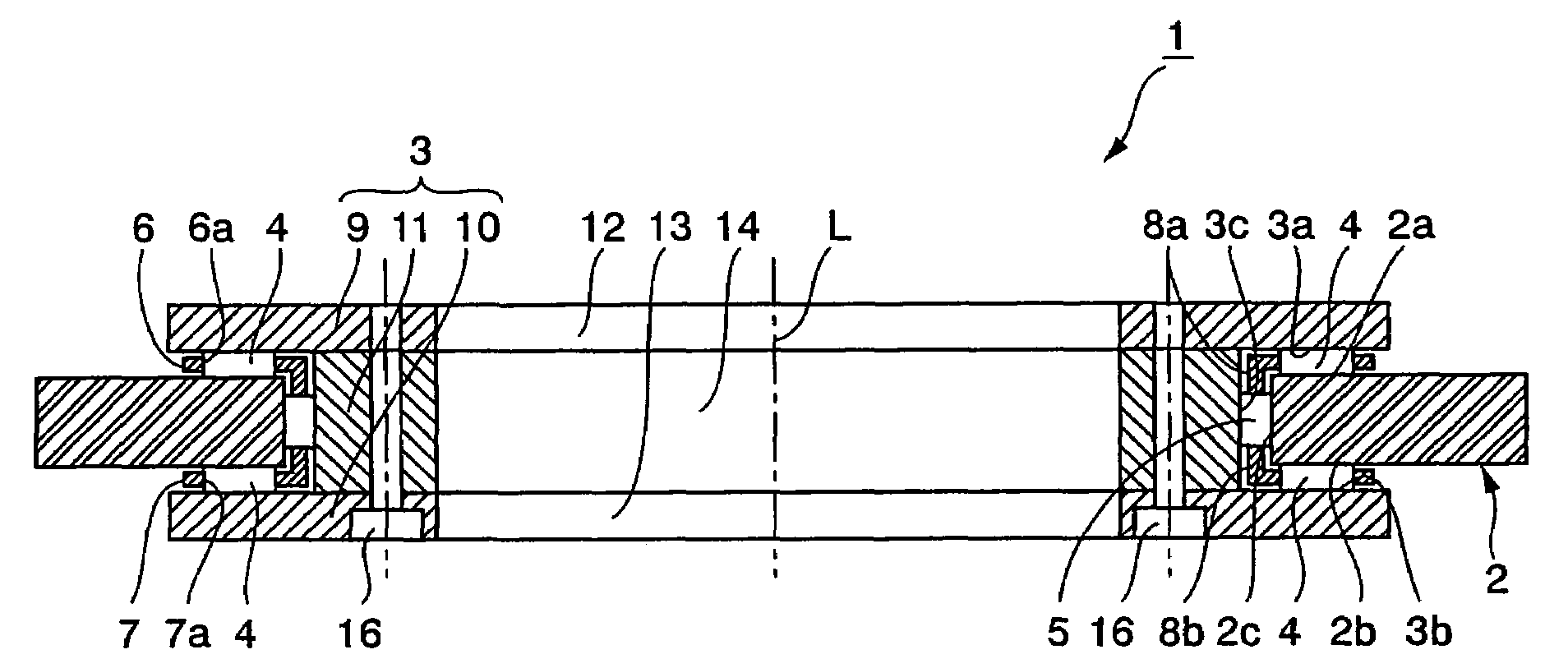
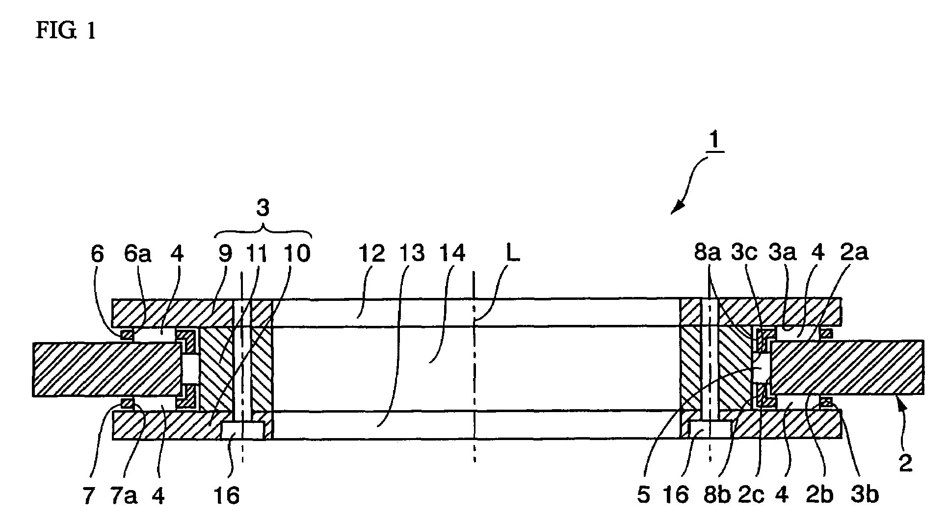
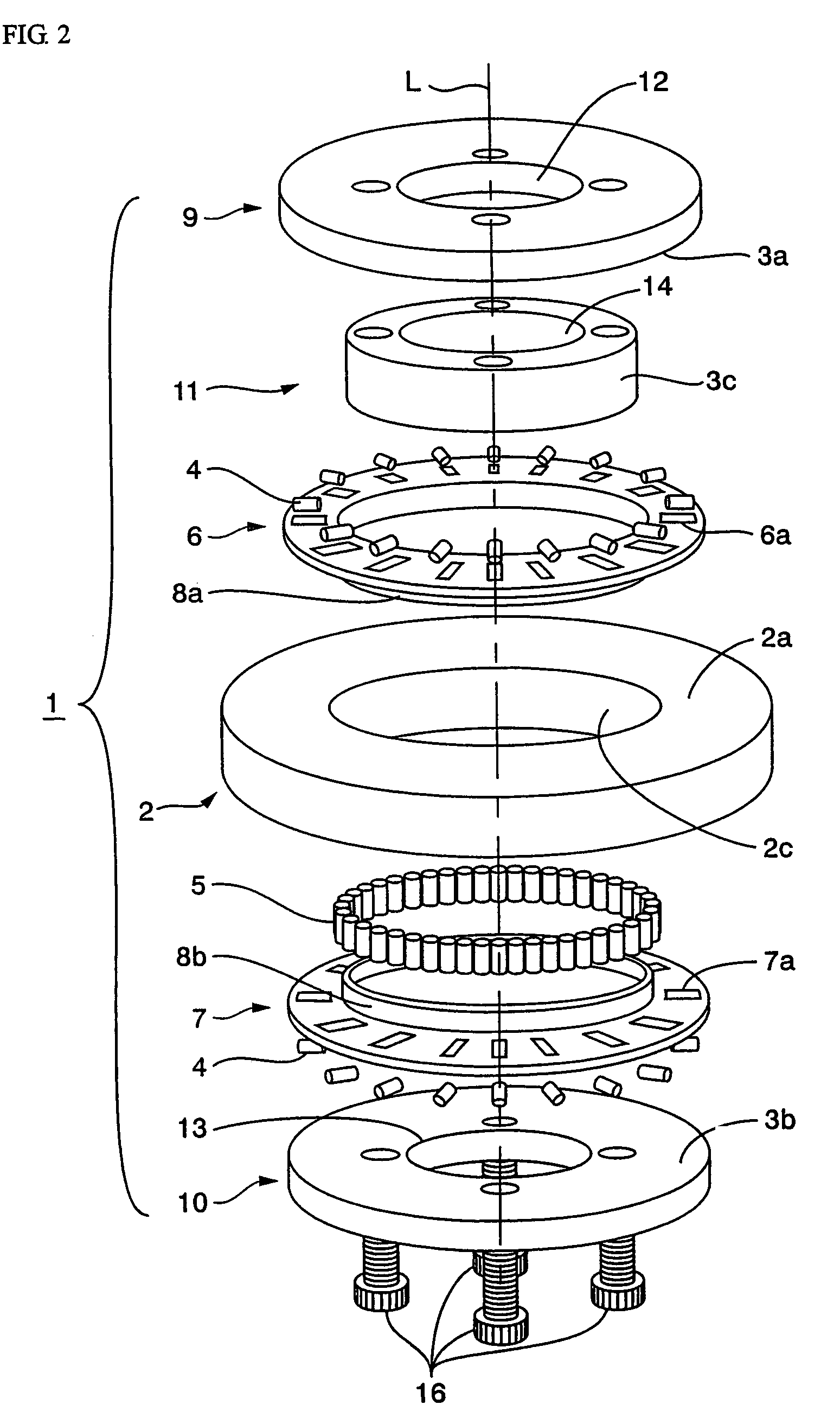
[0055]FIG. 1 is a cross-sectional view of a composite roll bearing according to the present invention, and FIG. 2 is an exploded perspective view thereof. As shown in these diagrams, a composite roll bearing 1 has an annular outer ring (first race ring) 2 comprising a circular inner peripheral surface 2c, and also comprising end-surface portions 2a, 2b linked to both ends of the circular inner peripheral surface 2c. The bearing also has an annular inner ring (second race ring) 3 in which a groove-shaped cross-sectional portion is formed and which comprises a first receiving surface 3a that faces the end-surface portion 2a at specified intervals, a second receiving surface 3b that faces the other end-surface portion 2b at specified intervals, and a third receiving surface 3c that faces the circular inner peripheral surface 2c at specified intervals.

[0056]FIG. 1 first annular race for thrust bearing is restricted by the end-surface portion 2a of the outer ring 2 and the first receivin...

embodiment 2

[0064]FIG. 4 is a cross-sectional view depicting another example of the composite roll bearing 1. The composite roll bearing 1A of the present example has an annular inner ring (first race ring) 3A, and an annular outer ring 2A (second race ring) having a groove-shaped cross section. The outer ring comprises first, second, and third receiving surfaces 2d, 2e, 2f that are placed opposite, and are separated by specified intervals from, outer peripheral side portions 3d, 3e at both end surfaces of the inner ring 3A, and from a circular outer peripheral surface 3f.

[0065]Thrust bearing rollers 4 capable of supporting thrust loads are located between one end-surface outer peripheral portion 3d of the inner ring 3A and the first receiving surface 2d of the outer ring 2A, and also between the other end-surface outer peripheral portion 3e of the inner ring 3A and the second receiving surface 2e of the outer ring 2A. Radial bearing rollers 5 capable of supporting radial loads are located bet...


PUM

PropertyMeasurementUnit
frictional resistanceaaaaaaaaaa
sliding frictional forceaaaaaaaaaa
frictional forceaaaaaaaaaa

Abstract

A composite roll bearing (1), comprising an outer ring (2) and an annular inner ring (3) of groove shape in cross section having first, second, and third receiving surfaces (3a, 3b, 3c) facing the both end face inner peripheral portions (2a, 2b) and the circular inner peripheral surface (2c) of the outer ring (2) at specified intervals. A plurality of rollers (4) for thrust bearing are installed between one end face portion (2a) of the outer ring (2) and the first receiving surface (3a) of the inner ring (3) and between the other end face (2b) of the outer ring (2) and the second receiving surface (3b) of the inner ring (3). A plurality of rollers (5) for radial bearing are installed between the circular inner peripheral surface (2c) of the outer ring (2) and the third receiving surface (3c) of the inner ring (3). The rollers (5) are restricted to move in a thrust direction by retainer portions (8a, 8a) formed at the inner ends of retainers (6, 7) for the rollers (4) for thrust bearing.

Description

TECHNICAL FIELD[0001]The present invention relates to a composite roll bearing that can bear loads in the radial direction and in the thrust direction. The present invention particularly relates to a composite roll bearing that has low frictional resistance and that is easily manufactured.BACKGROUND ART[0002]One commonly known example of a bearing for a rotating table of a machine tool or the like is a composite-type cylindrical roll bearing that can bear loads in both the radial and thrust directions. As shown in FIG. 5, a composite cylindrical roll bearing 100 has an annular outer ring 102 and an annular inner ring 103 having a groove-shaped cross section, and the inner ring comprises first, second, and third receiving surfaces 103a, 103b, 103c that face the inner peripheral portions 102a, 102b at both ends of the outer ring 102 and that also face a circular inner peripheral surface 102c of the outer ring at specified intervals. Thrust bearing rollers 104 for bearing thrust loads ...

Claims


Application Information

Patent Timeline
Patent Type & Authority Patents(United States)
IPC IPC(8): F16C19/54F16C33/46F16C19/38F16C19/48F16C33/48
CPCF16C19/381F16C33/4623F16C33/48F16C33/4641F16C2300/14F16C2240/84F16C2322/39
Inventor KIYOSAWA, YOSHIHIDEAOYAGI, HARUSHIGEHANAOKA, HIROKI
Owner HARMONIC DRIVE SYST IND CO LTD
Why Eureka
Try Eureka