Ultra wideband loop antenna

a loop antenna and wideband technology, applied in the direction of loop antennas, resonant antennas, radiating element structural forms, etc., can solve the problems of unstable impedance across the operating range, antennas can suffer from problematic spatial variation, and modified loop antennas sometimes have too high characteristic impedances for many applications

Inactive Publication Date: 2009-12-29
UNIV OF MASSACHUSETTS
View PDF15 Cites 175 Cited by
  • Summary
  • Abstract
  • Description
  • Claims
  • Application Information

AI Technical Summary

Problems solved by technology

However, modified loop antennas sometimes have a characteristic impedance that is too high for many applications.
Another problem with such antennas is that the impedance may not be stable across the operating range.
Also, these antennas can suffer from problematic spatial variation in the radiation pattern as a function of frequency.

Method used


Image

  • Ultra wideband loop antenna
  • Ultra wideband loop antenna
  • Ultra wideband loop antenna

Examples


Embodiment Construction

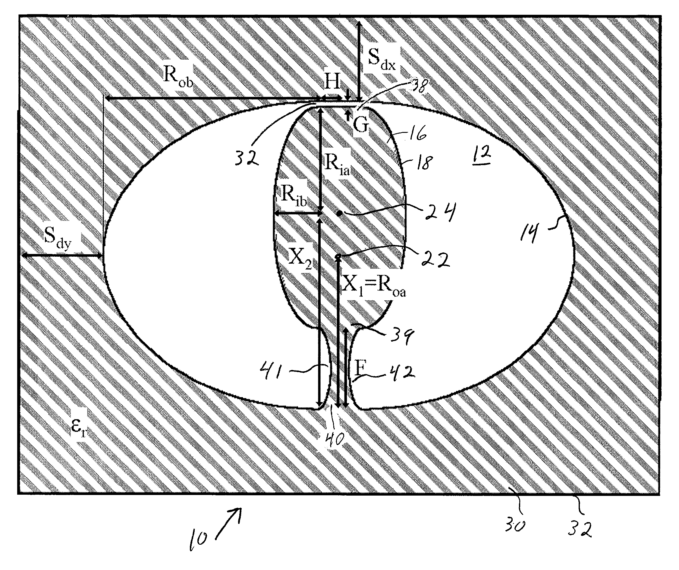
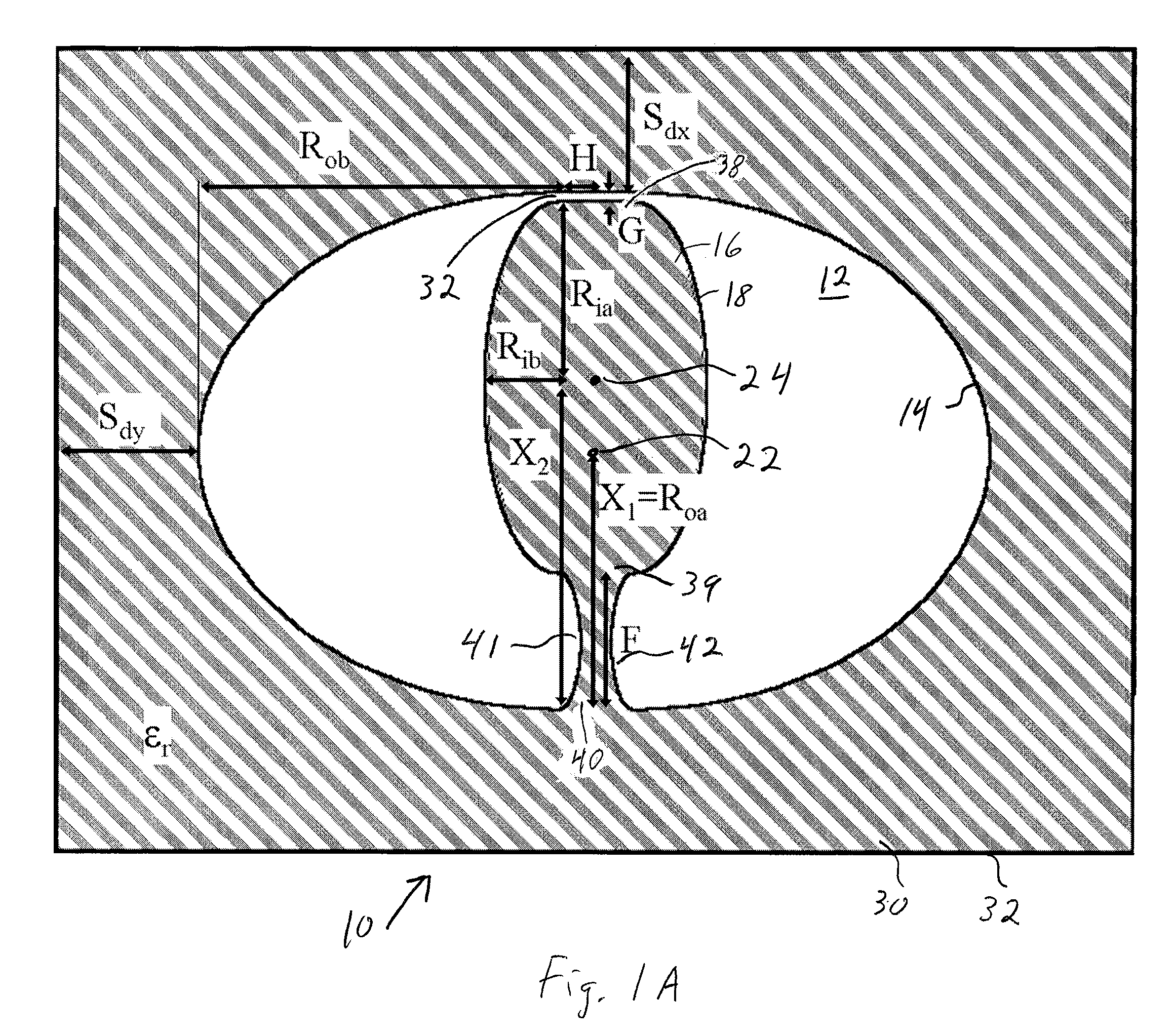
[0029]The invention may be accomplished in either a full loop or half loop antenna. The general shape of the embodiment of the inventive full loop antenna, FIG. 1A, is a large outer ellipse with a much smaller ellipse inside. The antenna is symmetric about the vertical (y) axis. The antenna is preferably accomplished with a planar conductor supported on a substrate; the substrate is shown in cross-hatching in FIG. 1A. Alternatively, the cross-hatched regions can comprise the conductor, in which case the large ellipse comprises an area from which the conductor has been removed; an example is shown in FIG. 1C.

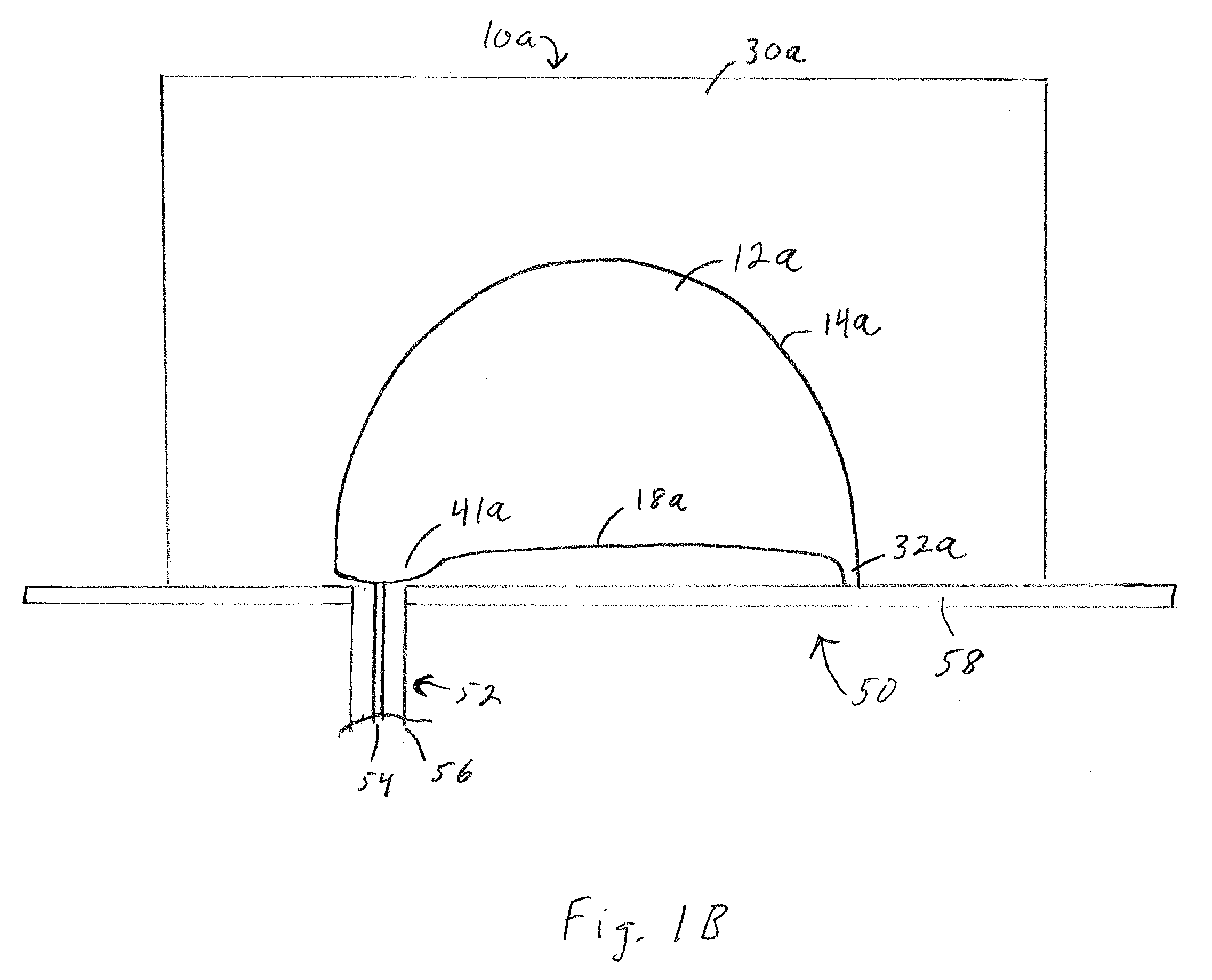
[0030]The embodiment of the half loop antenna, FIG. 1B, comprises one half of the full loop over an orthogonal ground plane, with the ground region of the loop electrically coupled to the ground plane.

[0031]The feed ends of the antenna are preferably bulbous or triangular, and wide. Unlike prior art ultra wideband antennas, the inventive antenna features a wide feed end and very ...


PUM


Abstract

An ultra wideband loop antenna having a planar antenna element defining an at least semi-elliptical perimeter having a major axis, a minor axis and a center. There is also an elongated, contiguous discontinuity in the antenna element that is symmetric about the antenna element minor axis, entirely located within the antenna element, and defining a discontinuity feed end located on the minor axis and spaced from one side of the antenna element perimeter by an element feed width, and further defining an opposed discontinuity ground end located on the minor axis and spaced from the opposing side of the antenna element perimeter by an element ground width, to define an antenna element ground portion, wherein the feed width is greater than the ground width. The antenna also has a feed region connecting the feed end of the discontinuity to the perimeter, to define antenna element feed ends that are adjacent to the feed region.

Description

GOVERNMENT RIGHTS[0001]This invention was made with Government support under US Army Research Office grant contract number DAAD19-01-1-0477. The Government has certain rights in the invention.FIELD OF THE INVENTION[0002]This invention relates to an ultra wideband loop antenna.BACKGROUND OF THE INVENTION[0003]Ultra wideband (UWB) antennas should operate across a bandwidth of at least about 1.5:1 [or 20% at the center frequency, according to the FCC standards] at microwave frequencies; one being from 3.1-10.6 GHz. The antenna should exhibit a reasonably stable input resistance and reactance across the frequency range to accomplish a voltage standing wave ratio (VSWR) lower than two across the antenna's average resistance.[0004]Ultra wideband loop antennas are typically embodied as either a half loop driven against an orthogonal ground plane, or a full loop. Such antennas typically have a feed region that is much narrower than the ground region. Examples are found in U.S. Pat. No. 3,01...

Claims


Application Information

Patent Timeline
Patent Type & Authority Patents(United States)
IPC IPC(8): H01Q1/14
CPCH01Q7/00
Inventor MARKLEIN, ERICSCHAUBERT, DANIEL
Owner UNIV OF MASSACHUSETTS
Why Eureka
Try Eureka