
Distortion compensating apparatus

a compensating apparatus and distortion technology, applied in the direction of digital transmission, amplifier modification to reduce non-linear distortion, baseband system details, etc., can solve the problem of phase difference not being detected correctly, and achieve the effect of shortening the updating interval of distortion compensation coefficients

Inactive Publication Date: 2009-12-29
FUJITSU LTD
View PDF12 Cites 5 Cited by
  • Summary
  • Abstract
  • Description
  • Claims
  • Application Information

AI Technical Summary

Benefits of technology

[0017]Accordingly, an object of the present invention is to so arrange it that a favorable, stabilized distortion compensating operation can be performed even if the phase difference between a reference signal and a feedback signal fluctuates owing to jitter or the like.
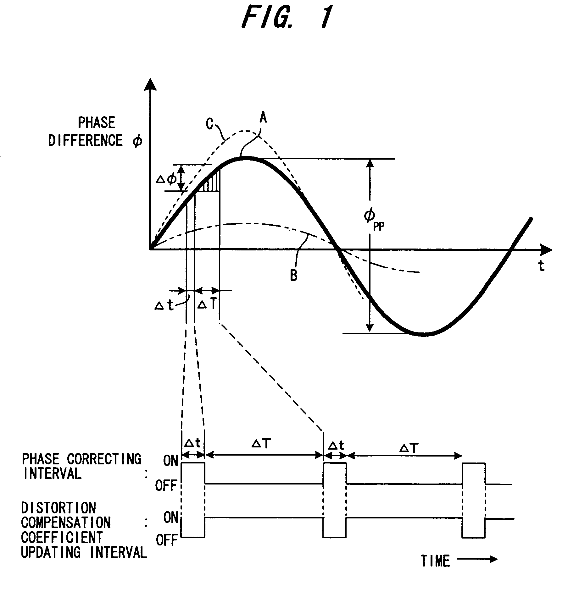
[0019]In accordance with this distortion compensating apparatus, the phase difference between the reference signal and the feedback signal is corrected periodically and the distortion compensation coefficient is updated only in an interval in which the phase difference is small. The distortion compensation coefficient can be made to converge rapidly, therefore, without being affected by the phase difference. As a result, a favorable, stabilized distortion compensating operation can be performed even if the phase difference between the reference signal and the feedback signal fluctuates.

Problems solved by technology

Further, phase difference cannot be detected correctly if the amplitude of the reference signal is zero or below the noise level.

Method used


Image

  • Distortion compensating apparatus
  • Distortion compensating apparatus
  • Distortion compensating apparatus

Examples


first embodiment

(B) First Embodiment

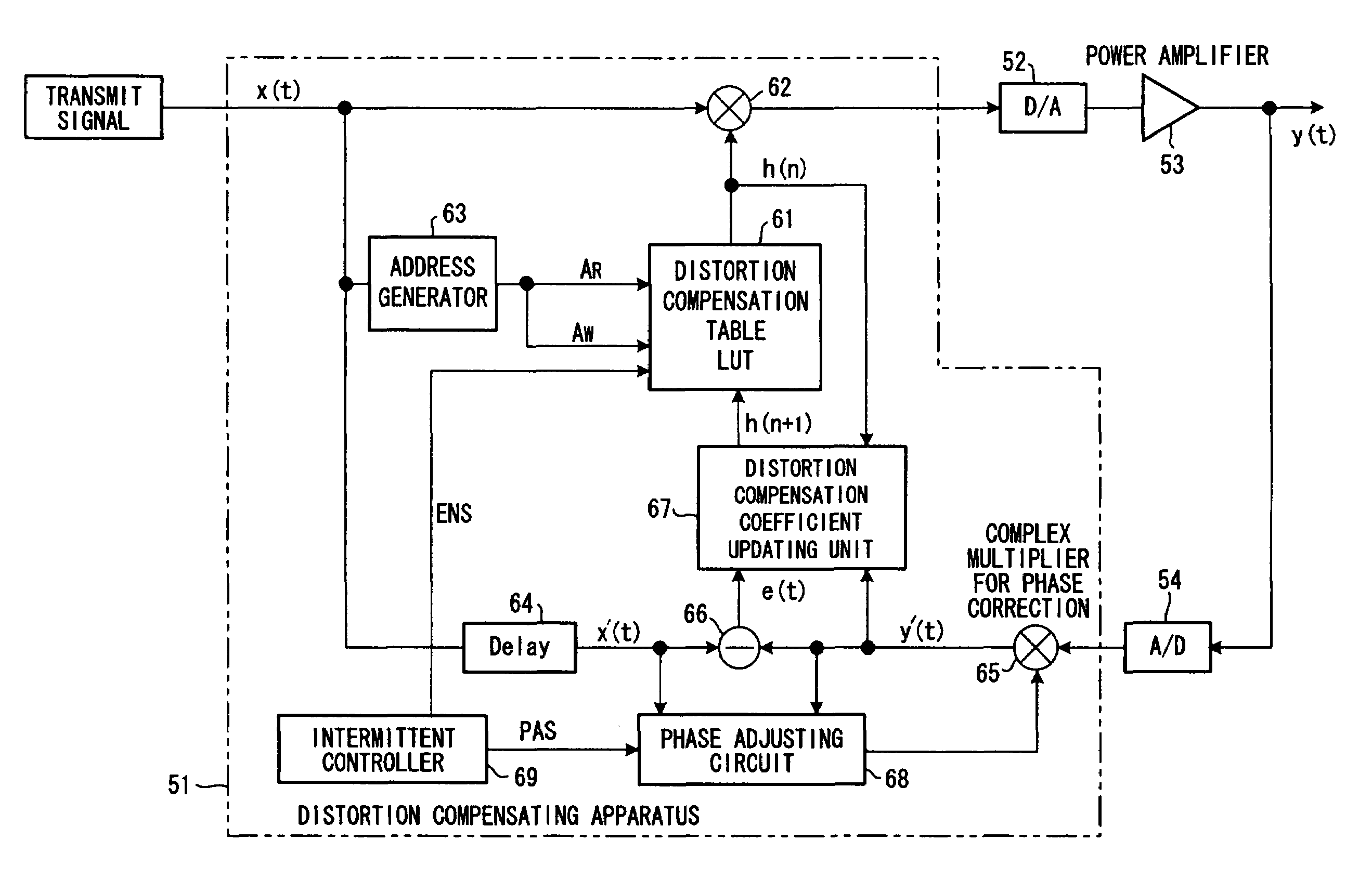
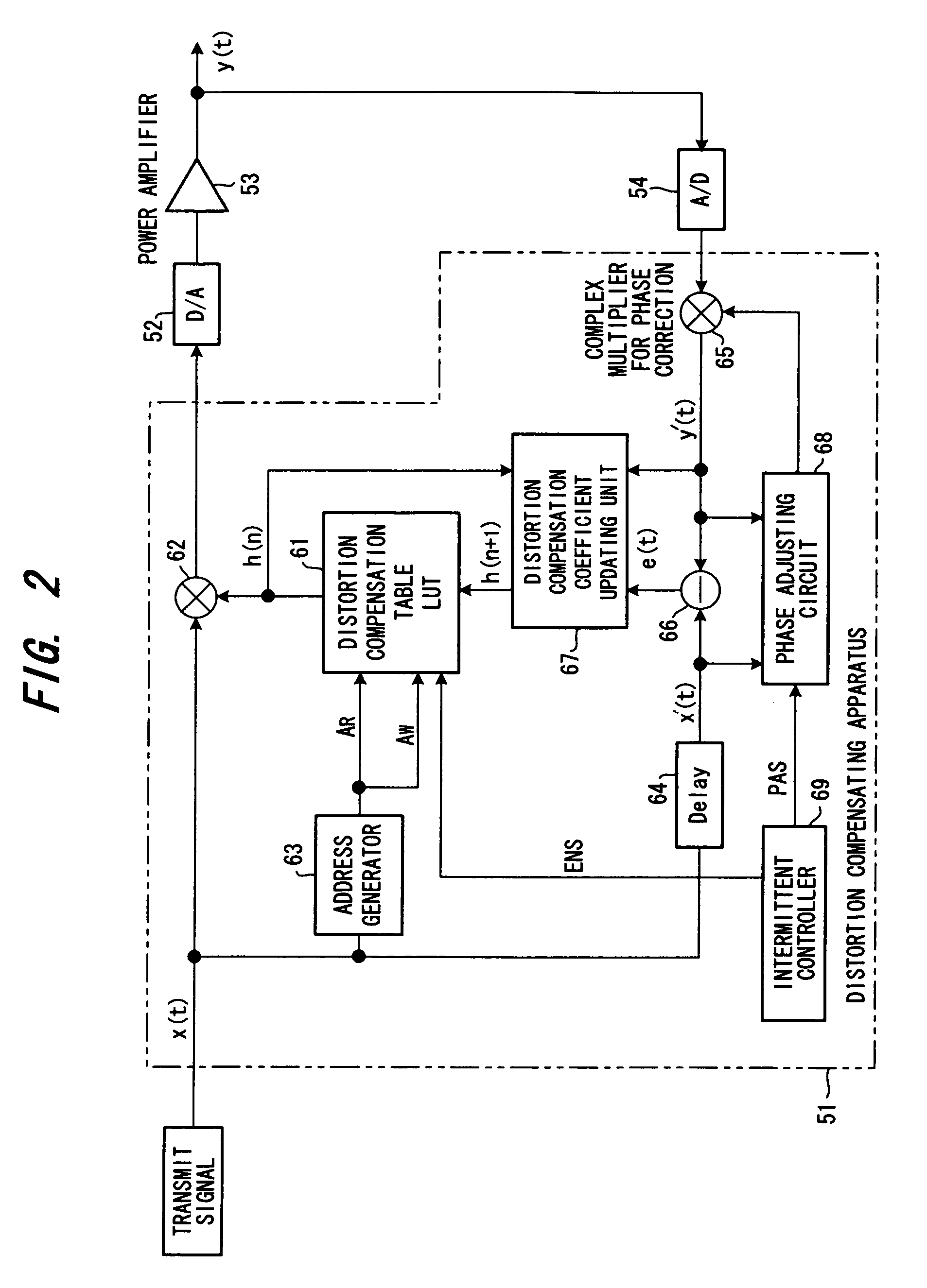
[0059]FIG. 2 is a block diagram of a distortion compensating apparatus according to a first embodiment.

[0060]A group of digital data (a transmit signal) sent from a transmit-signal generator (not shown) is subjected to distortion compensation processing by a distortion compensating apparatus 51 and then input to a DA converter 52. The latter converts the digital transmit signal to an analog signal and inputs the analog signal to a power amplifier 53 directly or via a quadrature modulator and frequency converter, which are not shown. The power amplifier 53 amplifies the input signal and the amplified signal is released into the atmosphere from an antenna. The output of the power amplifier 53 is input to an AD converter 54 directly or via a frequency converter or quadrature demodulator, which are not shown. The AD converter 54 converts the input signal to a digital signal and inputs the digital signal to the distortion compensating apparatus 51.

[0061]In the distort...

second embodiment

(C) Second Embodiment

[0071]FIG. 6 is a block diagram of a distortion compensating apparatus according to a second embodiment. Components identical with those of the first embodiment of FIG. 2 are designated by like reference characters. This embodiment differs in that an intermittent-control execution decision unit 70 is provided for determining whether or not intermittent control is to be performed.

[0072]In a case where the transmit signal has a large gap (i.e., is a special signal in which a signal of amplitude zero has been inserted intermittently) or has an amplitude that is on the order of the noise level, the phase adjusting circuit 68 can no longer correctly detect the phase difference between the reference signal and the feedback signal. In such case it is better to halt the phase correction or updating of the distortion compensation coefficient.

[0073]FIG. 7 is a flowchart of processing according to the second embodiment. In the second embodiment, the intermittent-control ex...

third embodiment

(D) Third Embodiment

[0081]FIG. 10 is a block diagram of a distortion compensating apparatus according to a third embodiment. Components identical with those of the first embodiment of FIG. 2 are designated by like reference characters. This embodiment differs in that ① a jitter-amount discriminating unit 73 is provided for discriminating amount of jitter; ② an update-interval decision unit 74 is provided for varying the length of the distortion compensation coefficient updating interval ΔT based upon the amount of jitter, and ③ the intermittent controller 69 raises the enable signal ENS to the high level in the distortion compensation coefficient updating interval ΔT decided and places the enable signal ENS at the low level in the phase correcting interval Δt.

[0082]The reason for controlling the distortion compensation coefficient updating interval ΔT is that if the amount of jitter is large, it is necessary to mitigate the influence of jitter by shortening the updating time of the ...


PUM


Abstract

A distortion compensating apparatus calculates a distortion compensation coefficient in such a manner that a difference signal between a reference signal, which is a transmit signal, and a feedback signal will be diminished, updates an old distortion compensation coefficient by the calculated distortion compensation coefficient and applies distortion compensation to the transmit signal based upon this distortion compensation coefficient. In this apparatus, a phase correcting interval, which is for correcting the phase difference between the reference signal and the feedback signal, and a distortion compensation coefficient updating interval are generated alternately, a correction is applied so as to null the phase difference in the phase correcting interval, and the distortion compensation coefficient is updated in the distortion compensation coefficient updating interval.

Description

CROSS-REFERENCE TO THE RELATED APPLICATION[0001]The present application is a continuation of International Application No. PCT / JP02 / 05323 which was filed on May 31, 2002, which is herein incorporated by reference.BACKGROUND OF THE INVENTION[0002]This invention relates to a distortion compensating apparatus and, more particularly, to a distortion compensating apparatus having a distortion compensation coefficient calculating unit, to which is input a difference signal between a reference signal that is a transmit signal and a feedback signal, for calculating a distortion compensation coefficient from an adaptive algorithm in such a manner that the difference signal will be diminished, a distortion compensation coefficient memory the stored content of which is updated by the distortion compensation coefficient calculated, and a distortion compensator for applying distortion compensation to the transmit signal based upon the distortion compensation coefficient.[0003]In wireless communi...

Claims


Application Information

Patent Timeline
Patent Type & Authority Patents(United States)
IPC IPC(8): H04K1/02H03F1/32
CPCH03F1/3247H03F2201/3233H03F2201/3231
Inventor ISHIKAWA, HIROYOSHIKUBO, TOKURONAGATANI, KAZUOOISHI, YASUYUKIHAMADA, HAJIMEFUDABA, NOBUKAZUMANIWA, TORUHAYASHI, HIROYUKI
Owner FUJITSU LTD
Learn More