Distortion compensating apparatus

a compensating apparatus and distortion technology, applied in the direction of digital transmission, amplifier modification to reduce non-linear distortion, baseband system details, etc., can solve the problem of phase difference not being detected correctly, and achieve the effect of shortening the updating interval of distortion compensation coefficients

Inactive Publication Date: 2005-03-03
FUJITSU LTD
View PDF6 Cites 38 Cited by
  • Summary
  • Abstract
  • Description
  • Claims
  • Application Information

AI Technical Summary

Benefits of technology

Further, an effect equivalent to a case where the distortion compensation coefficient updating interval is controlled is produced by controlling an updating time constant of distortion compensation coefficients in the distortion compensation coefficient calculating unit based upon the size of the phase difference between the reference signal and the feedback signal. For example, if the phase differe

Problems solved by technology

Further, phase difference cannot be detected correctly if the am

Method used


Image

  • Distortion compensating apparatus
  • Distortion compensating apparatus
  • Distortion compensating apparatus

Examples


first embodiment

(B) First Embodiment

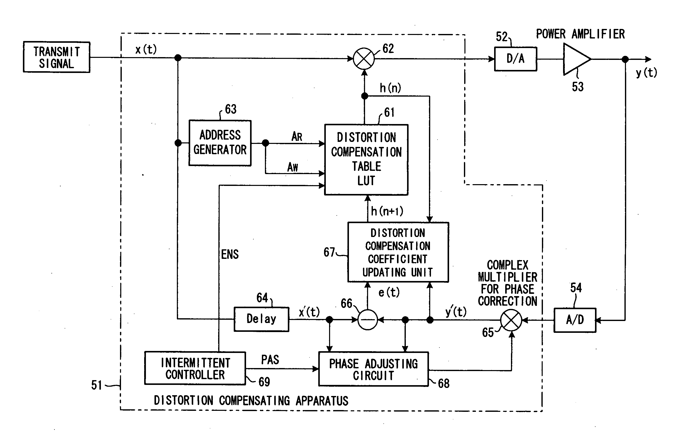
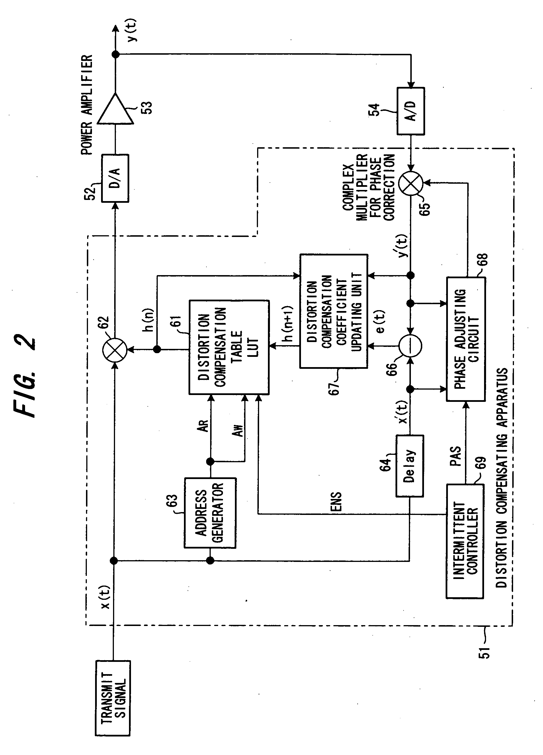
FIG. 2 is a block diagram of a distortion compensating apparatus according to a first embodiment.

A group of digital data (a transmit signal) sent from a transmit-signal generator (not shown) is subjected to distortion compensation processing by a distortion compensating apparatus 51 and then input to a DA converter 52. The latter converts the digital transmit signal to an analog signal and inputs the analog signal to a power amplifier 53 directly or via a quadrature modulator and frequency converter, which are not shown. The power amplifier 53 amplifies the input signal and the amplified signal is released into the atmosphere from an antenna. The output of the power amplifier 53 is input to an AD converter 54 directly or via a frequency converter or quadrature demodulator, which are not shown. The AD converter 54 converts the input signal to a digital signal and inputs the digital signal to the distortion compensating apparatus 51.

In the distortion compensati...

second embodiment

(C) Second Embodiment

FIG. 6 is a block diagram of a distortion compensating apparatus according to a second embodiment. Components identical with those of the first embodiment of FIG. 2 are designated by like reference characters. This embodiment differs in that an intermittent-control execution decision unit 70 is provided for determining whether or not intermittent control is to be performed.

In a case where the transmit signal has a large gap (i.e., is a special signal in which a signal of amplitude zero has been inserted intermittently) or has an amplitude that is on the order of the noise level, the phase adjusting circuit 68 can no longer correctly detect the phase difference between the reference signal and the feedback signal. In such case it is better to halt the phase correction or updating of the distortion compensation coefficient.

FIG. 7 is a flowchart of processing according to the second embodiment. In the second embodiment, the intermittent-control execution decisio...

third embodiment

(D) Third Embodiment

FIG. 10 is a block diagram of a distortion compensating apparatus according to a third embodiment. Components identical with those of the first embodiment of FIG. 2 are designated by like reference characters. This embodiment differs in that {circle over (1)} a jitter-amount discriminating unit 73 is provided for discriminating amount of jitter; {circle over (2)} an update-interval decision unit 74 is provided for varying the length of the distortion compensation coefficient updating interval ΔT based upon the amount of jitter, and {circle over (3)} the intermittent controller 69 raises the enable signal ENS to the high level in the distortion compensation coefficient updating interval ΔT decided and places the enable signal ENS at the low level in the phase correcting interval Δt.

The reason for controlling the distortion compensation coefficient updating interval ΔT is that if the amount of jitter is large, it is necessary to mitigate the influence of jitter b...


PUM


Abstract

A distortion compensating apparatus calculates a distortion compensation coefficient in such a manner that a difference signal between a reference signal, which is a transmit signal, and a feedback signal will be diminished, updates an old distortion compensation coefficient by the calculated distortion compensation coefficient and applies distortion compensation to the transmit signal based upon this distortion compensation coefficient. In this apparatus, a phase correcting interval, which is for correcting the phase difference between the reference signal and the feedback signal, and a distortion compensation coefficient updating interval are generated alternately, a correction is applied so as to null the phase difference in the phase correcting interval, and the distortion compensation coefficient is updated in the distortion compensation coefficient updating interval.

Description

BACKGROUND OF THE INVENTION This invention relates to a distortion compensating apparatus and, more particularly, to a distortion compensating apparatus having a distortion compensation coefficient calculating unit, to which is input a difference signal between a reference signal that is a transmit signal and a feedback signal, for calculating a distortion compensation coefficient from an adaptive algorithm in such a manner that the difference signal will be diminished, a distortion compensation coefficient memory the stored content of which is updated by the distortion compensation coefficient calculated, and a distortion compensator for applying distortion compensation to the transmit signal based upon the distortion compensation coefficient. In wireless communications in recent years, there is growing use of high-efficiency transmission using digital techniques. In instances where multilevel phase modulation is applied to wireless communications, a vital technique is one which ...

Claims


Application Information

Patent Timeline
IPC IPC(8): H03F1/32
CPCH03F1/3247H03F2201/3233H03F2201/3231
Inventor ISHIKAWA, HIROYOSHIKUBO, TOKURONAGATANI, KAZUOOISHI, YASUYUKIHAMADA, HAJIMEFUDABA, NOBUKAZUMANIWA, TORUHAYASHI, HIROYUKI
Owner FUJITSU LTD
Why Eureka
Try Eureka