Methods and Systems of Rapid Focusing and Zooming for Volumetric 3D Displays and Cameras

a volumetric 3d display and zooming technology, applied in the direction of camera focusing arrangement, printers, instruments, etc., can solve the problems of insufficient light passing through liquid lenses, difficulty in achieving piezoelectric lens achievement, and cost, and achieve rapid and repeated change, constant magnification, and rapid zoom

Inactive Publication Date: 2009-03-26
TSAO CHE CHIH
View PDF9 Cites 30 Cited by
  • Summary
  • Abstract
  • Description
  • Claims
  • Application Information

AI Technical Summary

Benefits of technology

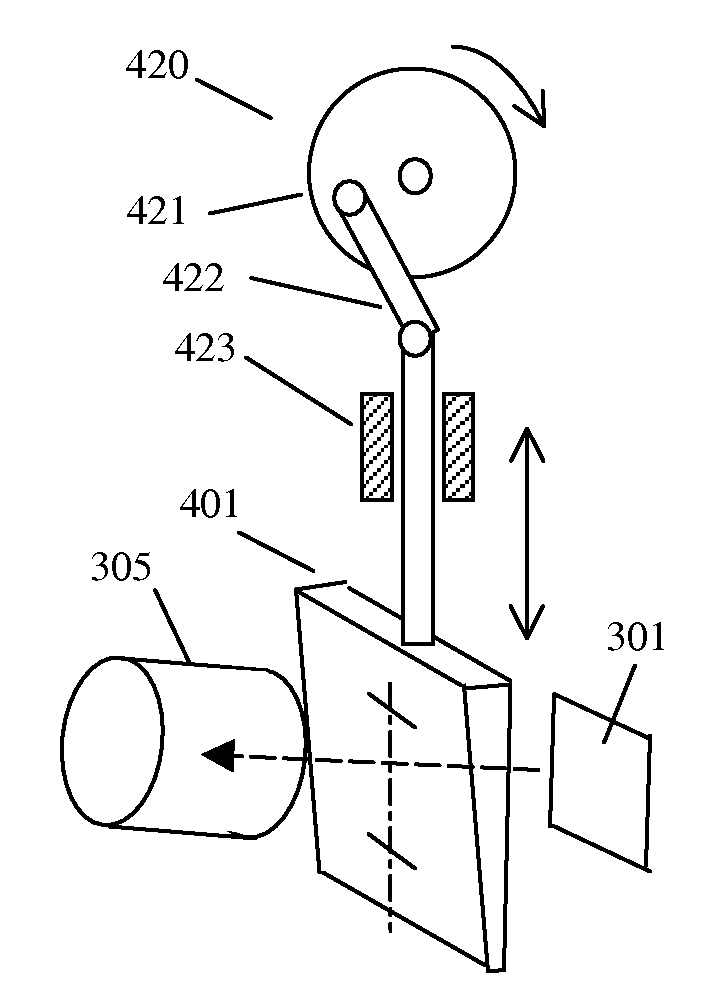
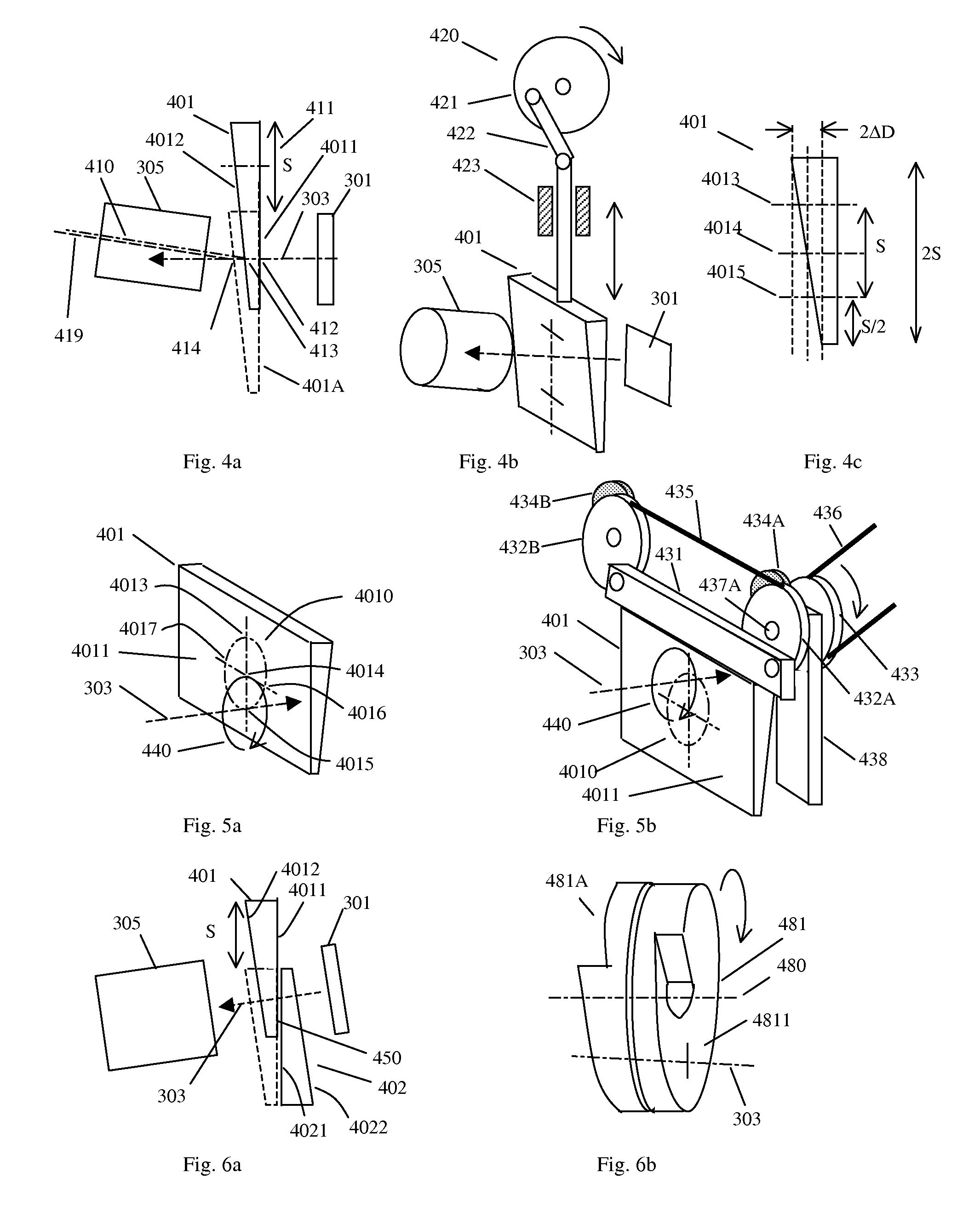
[0023]In this invention, rapid variable focusing is achieved by rapid and repeated change of the object distance, or the spacing between lens groups of the projection lens, or both. When the object distance and the spacing between the lens groups are changed simultaneously, the rapid focusing system becomes a rapid zooming system. Rapid zooming not only keeps the projected images in focus but also maintains a constant magnification.

Problems solved by technology

In these approaches, one major issue is to project images to the screen (or the liquid crystal screen) and keep the image in focus.
To achieve this by piezoelectric lens can be difficult and costly.
However, for the purpose of projecting bright, high quality image, liquid lens appears to be too small (only 2˜3 mm aperture) to pass enough light.
And because its principle is based on surface tension between two liquids, it is doubtful that larger lens can be made.
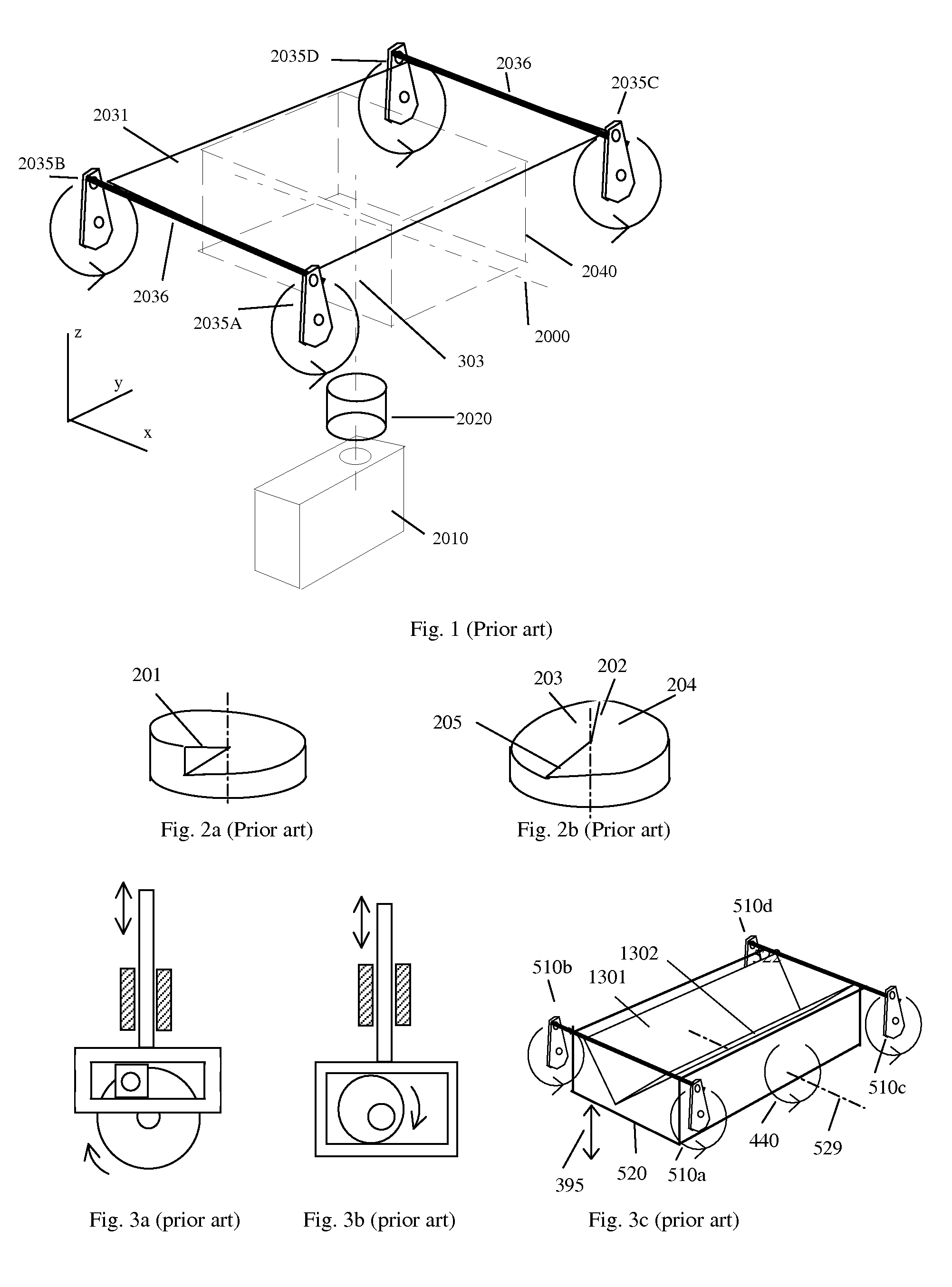
However, it is difficult to apply Sullivan's disks to systems with reciprocating screen or “Rotary Reciprocating” screen (of FIG. 1).
Therefore, this type of disk can not be used in both directions of the screen motion.
This is not desirable.
Although it is possible to use a combination of rotary motion with a rack and pinion system to turn the disk rotation into a sinusoidal function relative to time, the resulted system can be noisy and complicated.
Therefore, the disk of FIG. 2b is also undesirable.
Because a stair step must be wide enough to allow projection beam to pass through, a disk of reasonable size can only contain a very limited number of stair steps.
As a result, this type of disk is only suitable for displaying a very limited number of frames in the display volume.
This disk also has a discontinuous shape and is not suitable for a screen that moves back and forth.
However, these systems require certain amount of mechanical parts and take up certain amount of space.
The cost of linear stages, control systems and piezoelectric actuators can be significant.
A cam driving system can also be complicated to design and can be noisy.
In general, these methods of depth scanning are either slow or unable to cover large depth.

Method used


Image

  • Methods and Systems of Rapid Focusing and Zooming for Volumetric 3D Displays and Cameras
  • Methods and Systems of Rapid Focusing and Zooming for Volumetric 3D Displays and Cameras
  • Methods and Systems of Rapid Focusing and Zooming for Volumetric 3D Displays and Cameras

Examples


Embodiment Construction

[0059]In a typical V3D display, a small SLM (spatial light modulator) is used as the image source. The moving screen is large relative to the SLM. That is, magnification is large and Image distance is large relative to object distance. Referring to lens formula equations (A1) and (A2) of Appendix A, when a small object with a small So is projected to a large distance (large Si), a slight change of So creates large change of Si. Appendix B shows an example of projection design for a V3D display. A SLM of 8.75 mm height is projected to form a volume length of 5.625″ (142.88 mm). The required stroke (direct distance of screen motion from bottom to top) is 3″ (76.2 mm). A projection lens of f=36 mm is used. By lens formula equation (A1), a change of So of only 0.29 mm gives a change of Si of 3″ (76.2 mm). For cases of larger magnifications, the required change of So is even smaller. In addition, Appendix B indicates another important observation: the So to Si curve can be approximated b...


PUM


Abstract

This invention relates in general to methods and systems of rapid focusing and zooming for the applications in the projection of volumetric 3D images and in the imaging of 3D objects. Rapid variable focusing or zooming is achieved by rapid and repeated change of the object distance or the spacing between lens groups of the projection lens or a combination of both. One preferred approach inserts thin wedge prisms into the optical path and changes their positions relative to the optical path. This changes the thickness traveled through by the optical path and results in effective optical path length change. Another approach folds an optical path by mirrors and moves the mirrors to change the optical path length. For focusing purpose, small and precise displacement is achieved by moving a wedge-shaped optical device obliquely with respect to the optical path. The wedge-shaped optical device can be a thin wedge prism or a mirror on a wedge-shaped base. Optical layout analysis shows that the changes of the object distance, of the spacing between two lens groups and of the image distance are almost in proportion and can be correlated by linear relations. Therefore, the same type of motion function can be used to change these three optical path lengths to achieve focusing and constant magnification.

Description

CROSS-REFERENCE TO RELATED APPLICATIONS AND OTHER DOCUMENTS[0001]This application claims the benefit of prior U.S. provisional application No. 60 / 995,295, filed Sep. 26, 2007, the contents of which are incorporated herein by reference.[0002]This invention relates to the following US patents by Tsao: U.S. Pat. No. 5,954,414, U.S. Pat. No. 6,302,542 B1, U.S. Pat. No. 6,765,566 B1, and U.S. Pat. No. 6,961,045 B2. This invention also relates to the following co-pending U.S. application Ser. No. by Tsao: application Ser. No. 11 / 156,792 (claiming domestic priority of provisional application No. 60 / 581,422 filed Jun. 21, 2004). The above documents are therefore incorporated herein for this invention by reference.BACKGROUND OF THE INVENTION[0003]This invention relates in general to methods and systems of rapid focusing and zooming for the applications in the projection of volumetric 3D images and in the imaging of 3D objects.[0004]One category of V3D display generates V3D images by rapidly ...

Claims


Application Information

Patent Timeline
Patent Type & Authority Applications(United States)
IPC IPC(8): G02B26/08H04N13/02H04N13/20H04N13/393
CPCG02B7/102G03B3/10H04N13/0493H04N13/02G03B13/34Y10S359/90H04N13/20H04N13/393
Inventor TSAO, CHE-CHIH
Owner TSAO CHE CHIH
Why Eureka
Try Eureka