Air bag system for motor vehicles

a technology for air bags and motor vehicles, applied in the direction of vehicle components, pedestrian/occupant safety arrangements, vehicular safety arrangments, etc., can solve the problem of not having a supporting surface, and achieve the effect of improving the support effect, facilitating filling, and facilitating filling

Active Publication Date: 2010-01-05
AUTOLIV DEV AB
View PDF18 Cites 8 Cited by
  • Summary
  • Abstract
  • Description
  • Claims
  • Application Information

AI Technical Summary

Benefits of technology

[0006]The present invention seeks to develop an air bag system such that protection of the occupant in the event of a side impact collision is further improved.
[0007]In at least one embodiment of the present invention, a housing that accommodates the non-inflated air bag is arranged below the windowsill in such a way that between the exit opening of the housing and the upper edge of the windowsill, there is a supporting surface for the air bag. This supporting surface can be part of the inner lining of the door or part of the housing. The air bag itself features a main chamber with an impact surface and a supporting chamber that is situated between the main chamber and the supporting surface. The main chamber is therefore not supported directly by the supporting surface, but only indirectly by the supporting chamber. In this way, a reasonably thick air bag is provided in the area of the supporting surface, so as to improve the supporting effect.
[0008]Dividing the air bag into two parts in the area of the supporting surface also provides the possibility of configuring the supporting chamber with a height that is lower than that of the main chamber, which, with the same gas generator performance, may lead to correspondingly faster filling, without having to accept losses with regard to the performance of the system. In addition, due to the configuration of the air bag system in accordance with the invention, it may be possible to position the supporting surface relative to the occupant so as to improve the retaining effect on the occupant, particularly through an early interfacing between the shoulder and head area of the occupant with the impact surface of the air bag.

Problems solved by technology

Consequently no supporting surface may be available at the height of the occupant's head.

Method used


Image

  • Air bag system for motor vehicles
  • Air bag system for motor vehicles
  • Air bag system for motor vehicles

Examples


Embodiment Construction

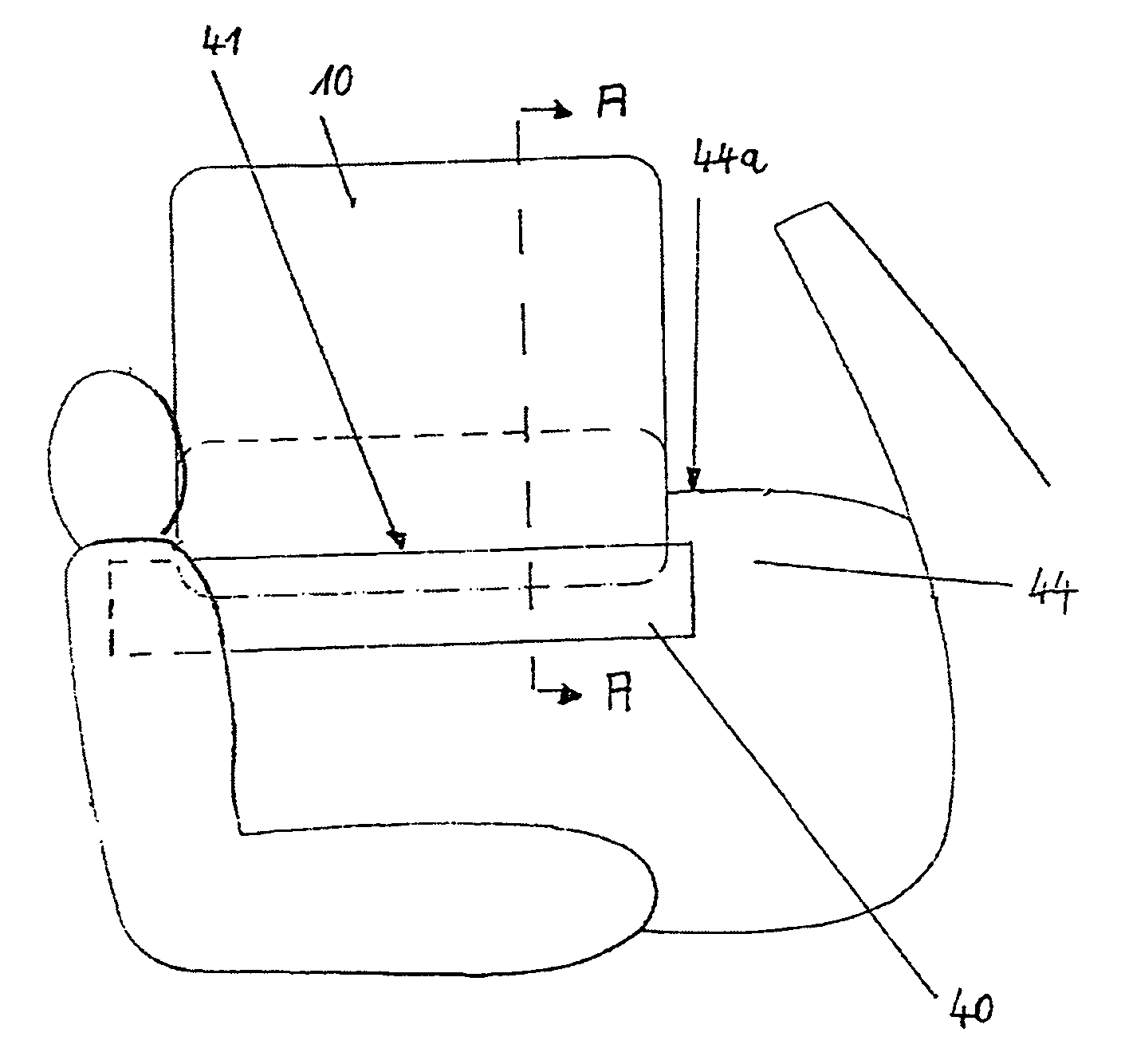
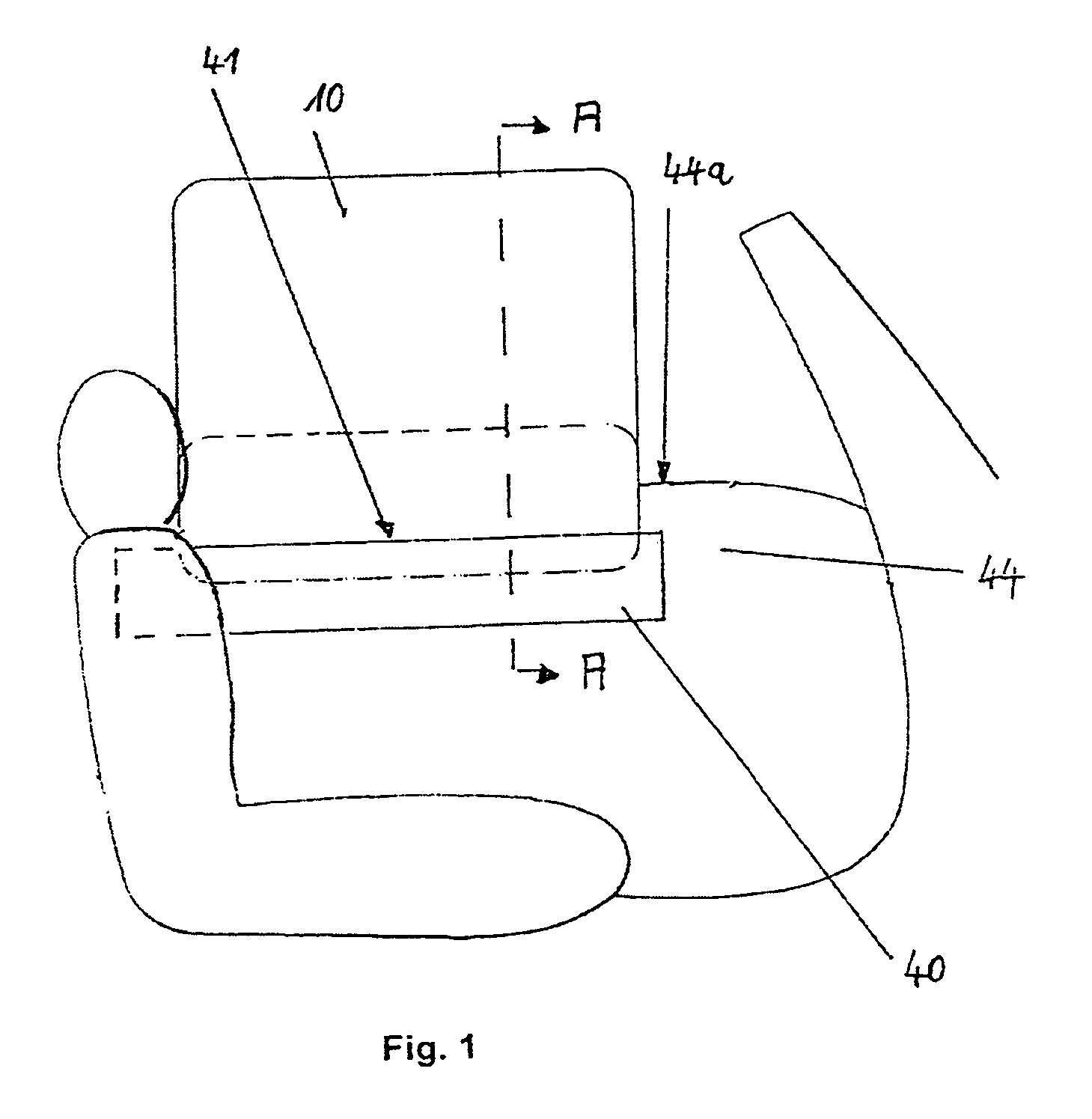
[0013]FIG. 1 shows a schematic view, from the inside, of the front-seat area of an open-topped or convertible vehicle. On the interior side of the door 44 below the upper edge 44a of the windowsill, the housing 40 is arranged, which completely accommodates the air bag 10 in its non-inflated state. FIG. 1 shows the state in which the air bag 10 is completely inflated, whereby a major part of the air bag is disposed above the upper edge 44a of the windowsill. The housing 40 can be an integral part of the interior lining of the door or otherwise. A gas generator is also arranged (not shown in FIG. 1) proximate the housing (e.g. in or on the housing 40).

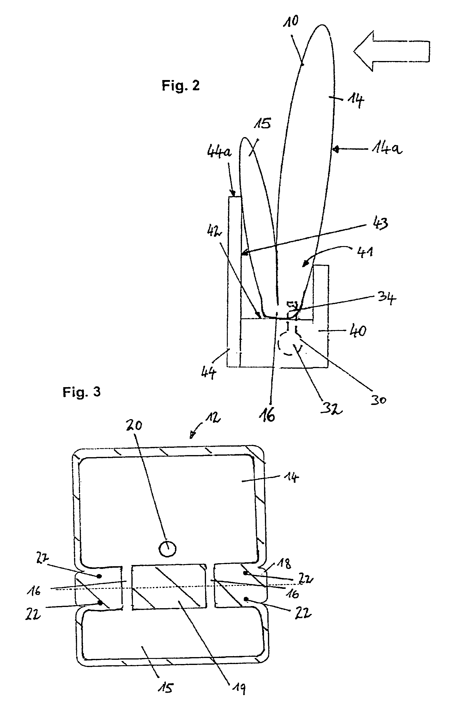
[0014]The structure and functioning of the air bag system is illustrated in FIG. 2, which is a cross-sectional view along section A-A in FIG. 1. The air bag 10 features a main chamber 14 and a supporting chamber 15, which are connected by means of filling chambers 16. The housing 40 is arranged below the upper edge 44a of the windowsill ...


PUM


Abstract

In at least one embodiment, an air bag system comprises an air bag having an impact surface which in a non-inflated state is arranged in a housing located below the upper edge of a windowsill of a vehicle door. In an inflated state, at least part of the impact surface is positioned above the windowsill. There is a supporting surface for the air bag below the upper edge of the windowsill. The air bag defines a main chamber and a supporting chamber. The impact surface forms part of the main chamber. The supporting chamber, in an inflated state, is situated between the main chamber and the supporting surface and is supported at least in part by the supporting surface.

Description

CROSS REFERENCE TO RELATED APPLICATIONS[0001]This application claims priority to PCT patent application WO2007 / 036336 filed Sep. 25, 2006 and DE 10 2005-046 267.7 filed on Sep. 27, 2005.FIELD OF THE INVENTION[0002]The invention relates to an air bag system for motor vehicles.BACKGROUND OF THE INVENTION[0003]In the state of the art, so-called side air bags for motor vehicles are known that are arranged either in the seat or in the lateral structure of the motor vehicle below the side window. Such side air bags are intended to protect the head and thorax of the occupant in the event of a side impact. As the head, and usually also part of the thorax of the occupant are above the windowsill of the side door, i.e. at the height of the side window, the side air bag is usually supported against the side window and most often, at least in part, against the B-pillar.[0004]In convertibles and roadsters in particular—and to some extent in coupes as well—the B-pillar may be absent and the vehic...

Claims


Application Information

Patent Timeline
Patent Type & Authority Patents(United States)
IPC IPC(8): B60R21/16B60R21/21
CPCB60R21/21B60R21/233B60R2021/161
Inventor MANSSON, JOHANKJELL, FREDRIKOHRVALL, HENRIKPALO, ANDERS
Owner AUTOLIV DEV AB
Why Eureka
Try Eureka