Manually operated vacuum pump and refill device

a vacuum pump and manual operation technology, applied in the direction of liquid fuel engines, liquid handling, positive displacement liquid engines, etc., can solve the problem of vaporization of coolant water, and achieve the effect of convenient and rapid vacuuming

Inactive Publication Date: 2010-01-05
LIH YANN INDAL
View PDF23 Cites 2 Cited by
  • Summary
  • Abstract
  • Description
  • Claims
  • Application Information

AI Technical Summary

Benefits of technology

[0006]It is an object to provide a device such that a radiator can be easily and quickly vacuumed.

Problems solved by technology

However, after a period of time, the cooling water will vaporize and need to be refilled from time to time.

Method used


Image

  • Manually operated vacuum pump and refill device
  • Manually operated vacuum pump and refill device
  • Manually operated vacuum pump and refill device

Examples


Embodiment Construction

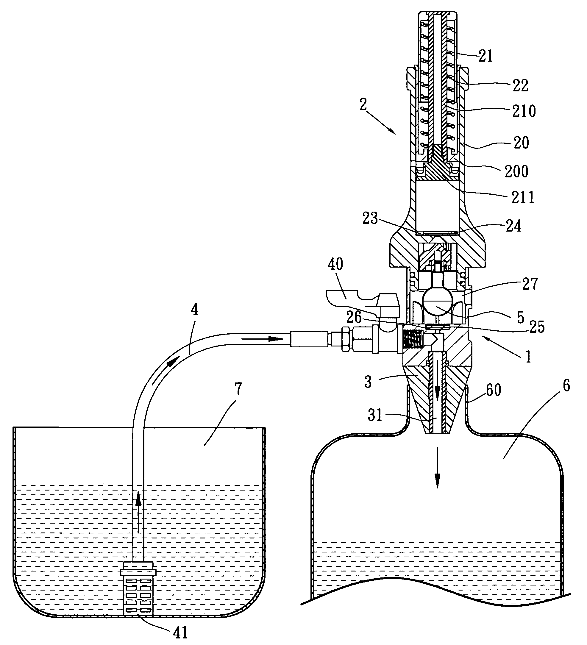
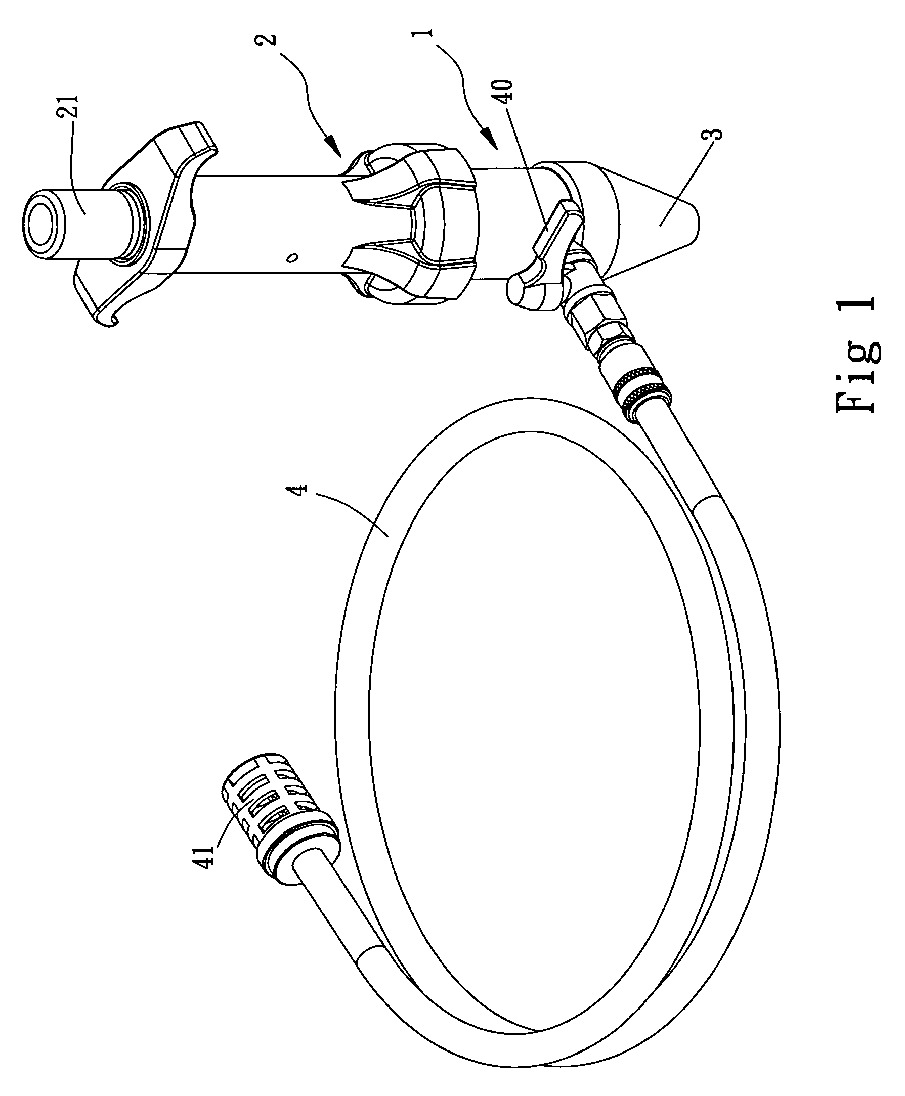
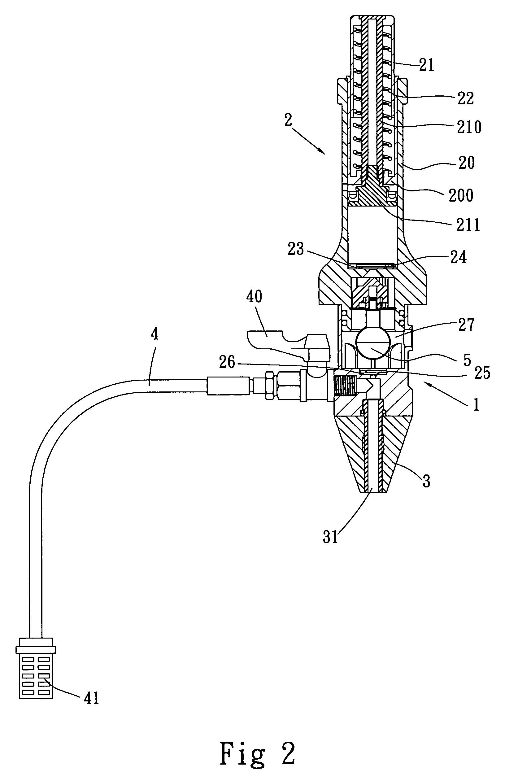
[0017]Referring to FIG. 1, a perspective view of a manually operated vacuum pump and refill device made in accordance with the present invention; while FIG. 2 further discloses an internal structure of the device. The device includes a body 1 on top there is a vacuum pump 2 attached, and a lower portion of the body 1 is attached with an elastic adapter 3. The adapter 3 has a central channel 31 in communication with the body 1. The body 1 further includes an inlet in which a water supply 4 is connected. A control valve 40 is arranged on the water supply 4 before it reaches to the body 1. A filter 41 is arranged in the water supply 4 at an end thereof.

[0018]The vacuum pump 2 includes an outer pipe 20 with a stopper 200 located at a Certain depth from a top of the outer pipe 20. A piston 21 is assembled within the outer pipe 20 and enveloped with a coil spring 22 assembled along a stud 210. An end of the coil spring 22 abuts against the stopper 200. The stud 210 extends through the sto...


PUM


Abstract

A manually operated vacuum pump and refill device includes a body on top with a vacuum pump attached, and a lower portion of the body is arranged with an elastic adapter. The adapter has a central channel in communication with the body. The body includes an inlet in which a water supply is connected. A control valve is arranged on the water supply before it reaches to the body. The vacuum pump is further arranged with a check valve with respect to the body. The body is also arranged with a check valve securely positioned with a C-clip. The check valve is provided with a float moveably within a chamber thereof.

Description

BACKGROUND OF THE INVENTION[0001]1. Field of the Invention[0002]The present invention relates to a manually operated vacuum pump, and more particularly to a manually operated vacuum pump and refill device in which liquid can be rapidly refilled after a radiator is vacuumed.[0003]2. Description of Prior Art[0004]A radiator of an automobile plays a great role in dissipating heat generated by an engine. The radiator generally is a closed heat-exchange system and by cycling the water contained therein, heat generated from the engine can be dissipated. However, after a period of time, the cooling water will vaporize and need to be refilled from time to time. Ideally, it is preferable that there is no air trapped within the closed-system since air trapped inside the radiator will negatively influence the heat dissipating rate. As a result, it is preferable to vacuum the radiator first such that no air is trapped therein, and then refill the cooling water. By this arrangement, this will be...

Claims


Application Information

Patent Timeline
Patent Type & Authority Patents(United States)
IPC IPC(8): F04B23/00B67C3/16F04B23/02F04B41/00F04B41/02F04B53/00F04B53/10F04F3/00
CPCF04B33/00F04F3/00Y10T137/3109
Inventor LIAO, LIN PO
Owner LIH YANN INDAL
Why Eureka
Try Eureka