Digital phase locked loop

a technology of phase locking loop and digital phase, applied in the direction of pulse automatic control, electric apparatus, etc., can solve the problems of limiting the performance of the analog pll is limited, and the performance of the pll is much better

Active Publication Date: 2010-01-05
ZARLINK SEMICON LTD
View PDF12 Cites 9 Cited by
  • Summary
  • Abstract
  • Description
  • Claims
  • Application Information

AI Technical Summary

Problems solved by technology

In the design of a PLL a critical issue is the design of the phase detector as it includes a number of factors that limit performance of the PLL.
Analog PLL's have several limitations for which digital PLLs have a much better performance.
However, digital PLLs are susceptible to the additional of noise that is added to the feedback signal during the re-sampling process.

Method used


Image

  • Digital phase locked loop
  • Digital phase locked loop
  • Digital phase locked loop

Examples


Embodiment Construction

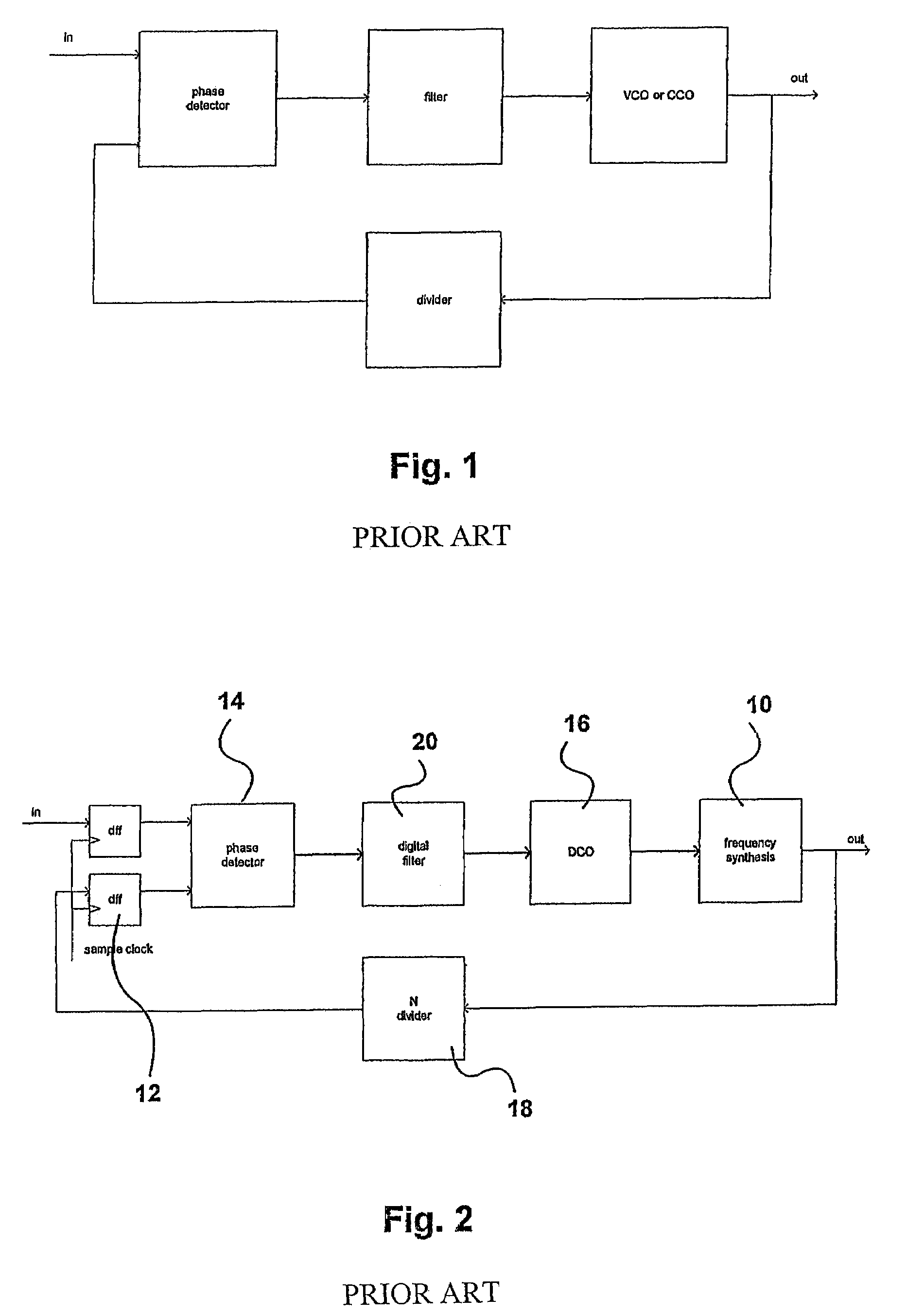
[0015]Referring again to FIG. 2, the output of the frequency synthesizer 10 is passed through sampling unit D-type flip flops 12 to an input of the phase detector 14, which is a detector with negative and positive inputs. It will be observed that the feedback signal from the frequency synthesizer 10 is actually a close derivative of the output of the DCO 16.

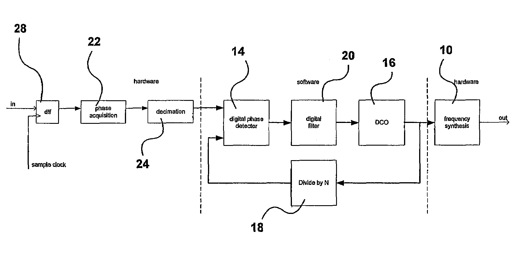
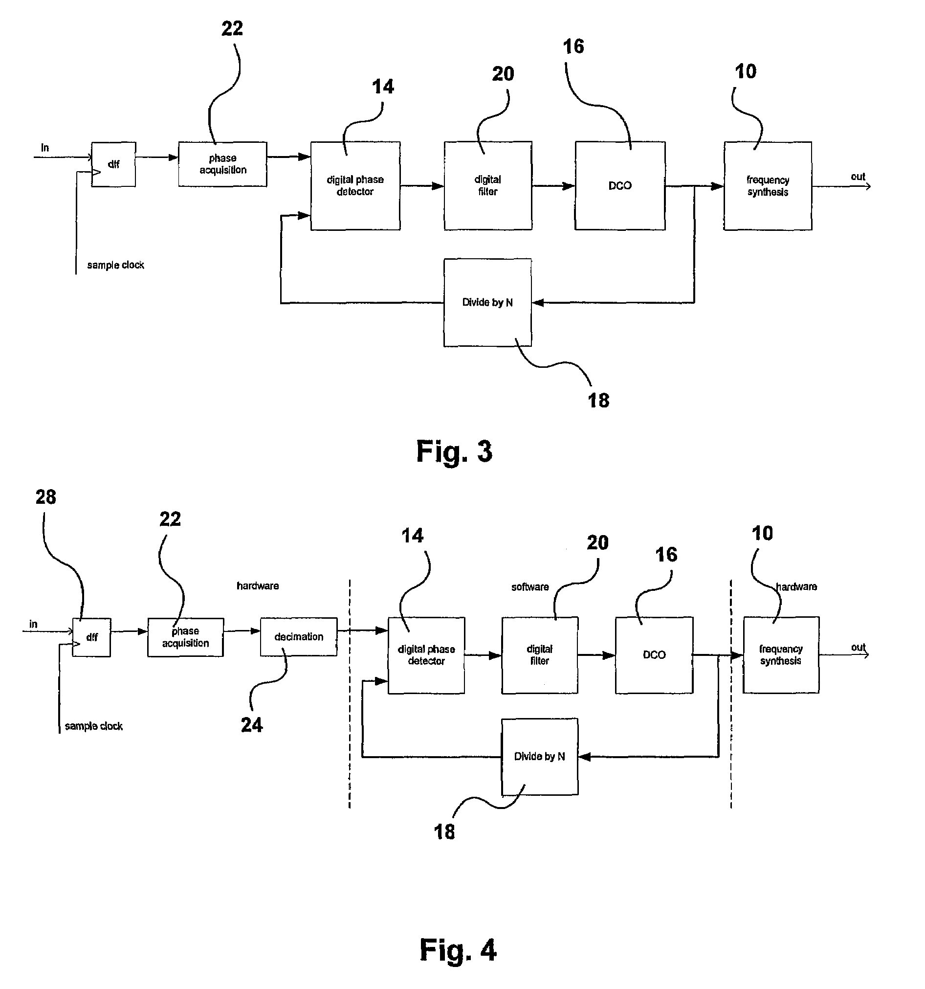
[0016]It is thus possible to generate the phase feedback signal not as a real frequency but as a digital word by taking the DCO phase (frequency) value and multiplying / dividing it to map it to another phase (frequency) in a straightforward mathematical operation: multiplication with a (fractional) number which is identical with division by a fractional number. If that is done, the phase comparison at the input of the PLL must be performed with a signal from a block that acquires the phase of the input signal and compares that with the feedback phase word.

[0017]The sampling of a real feedback signal actually does not yield informa...


PUM


Abstract

A digital phase locked loop includes a phase acquisition unit for producing a digital representation of the phase of a reference signal, a digital phase detector having a first input receiving a digital signal from, or derived from, the output of the phase acquisition unit, digital loop filter filtering the output of the digital phase detector, and a digital controlled oscillator generating an output signal under the control of the digital loop filter. A digital feedback loop provides a second input to the digital phase detector from the output of the digital controlled oscillator.

Description

FIELD OF THE INVENTION[0001]This invention relates to a digital phase locked loop, and in particular to a digital phase locked loop (PLL) without a physical feedback signal.BACKGROUND OF THE INVENTION[0002]In the design of a PLL a critical issue is the design of the phase detector as it includes a number of factors that limit performance of the PLL. A conventional analog PLL typically is constructed as shown in FIG. 1. In this Figure a phase detector determines the difference between two phase signals, one being the feedback signal and the other being the reference signal. The output of the phase detector is fed to a filter section, which may for instance be P type only (Proportional) but typically will be PI type (Proportional-Integral), providing a so-called type II PLL. The filter feeds to a controlled oscillator, which in FIG. 1 is a voltage or current controlled oscillator. The frequency generated by the controlled oscillator is divided and fed back to the input of the phase[00...

Claims


Application Information

Patent Timeline
Patent Type & Authority Patents(United States)
IPC IPC(8): H03L7/06
CPCH03L7/085H03L7/091H03L7/0991H03L7/18H03L2207/50
Inventor VAN DER VALK, ROBERTUS LAURENTIUSSCHRAM, PAUL HENDRICUS LODEWIJK MARIADE RIJK, JOHANNES HERMANUS ALOYSIUS
Owner ZARLINK SEMICON LTD
Why Eureka
Try Eureka