Antenna

a technology of antennas and antennas, applied in the field of antennas, can solve the problems of increasing the vulnerability to electromagnetic interference from the ambient environment, serious fall in the wireless communication quality of portable electrical devices, etc., and achieve the effects of reducing high-frequency interference, improving wireless communication quality, and reducing high-frequency interferen

Inactive Publication Date: 2010-01-05
CHENG UEI PRECISION IND CO LTD
View PDF11 Cites 4 Cited by
  • Summary
  • Abstract
  • Description
  • Claims
  • Application Information

AI Technical Summary

Benefits of technology

[0006]Accordingly, an object of the present invention is to provide an antenna which exhibits excellent anti-interference characteristic for use in a portable electrical device.
[0009]As described above, according to a first aspect of the present invention, the second radiating conductor used to receive electromagnetic signal of the low frequency band almost encircles the first radiating conductor used to receive electromagnetic signal of high-frequency band, that is, the first radiating conductor is separated away from other electrical devices arranged therearound via the second radiating conductor, which can reduce the high-frequency interference between the antenna and other electrical devices. According to a second aspect of the present invention, the wireless communication device with the antenna and acoustic component mounted therein is improved the wireless communication quality because of the acoustic component surrounded by the radiating end and the second connecting portion so as to reduce the high-frequency interference between the antenna and acoustic component.

Problems solved by technology

However, since a conventional antenna is mounted in a small space of a portable electrical device, the conventional antenna increases the vulnerability to the electromagnetic interference from the ambient environment, that is, the conventional antenna is easy to get influenced by neighbor electrical components, for example acoustic component.
As a result, the resonant frequency of the conventional antenna is changed adversely or its radiation characteristic deteriorates and consequently, wireless communication quality of the portable electrical device falls seriously.

Method used


Image

  • Antenna
  • Antenna
  • Antenna

Examples


Embodiment Construction

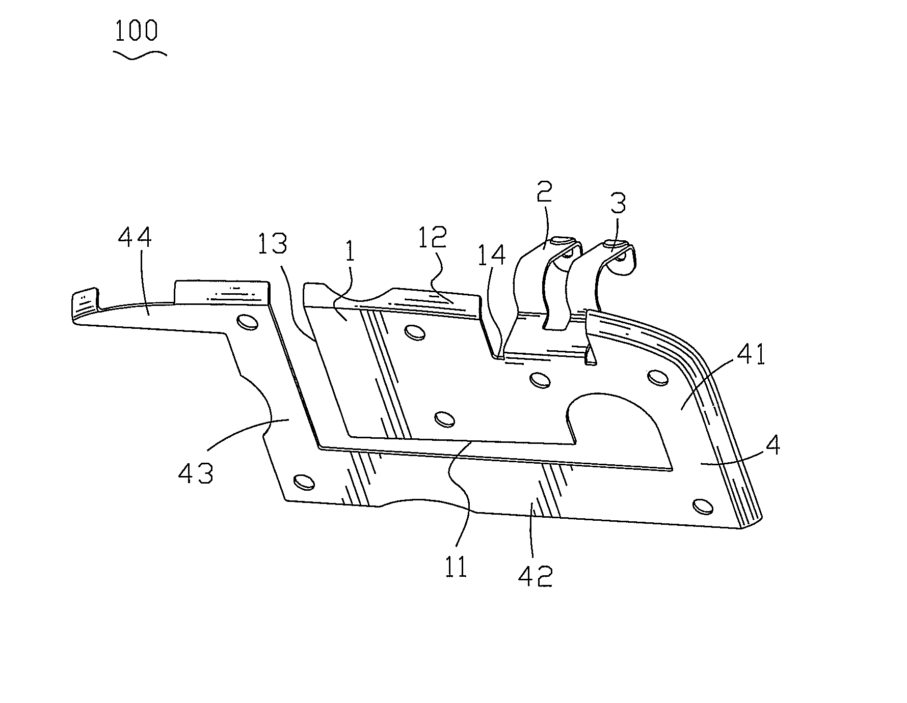
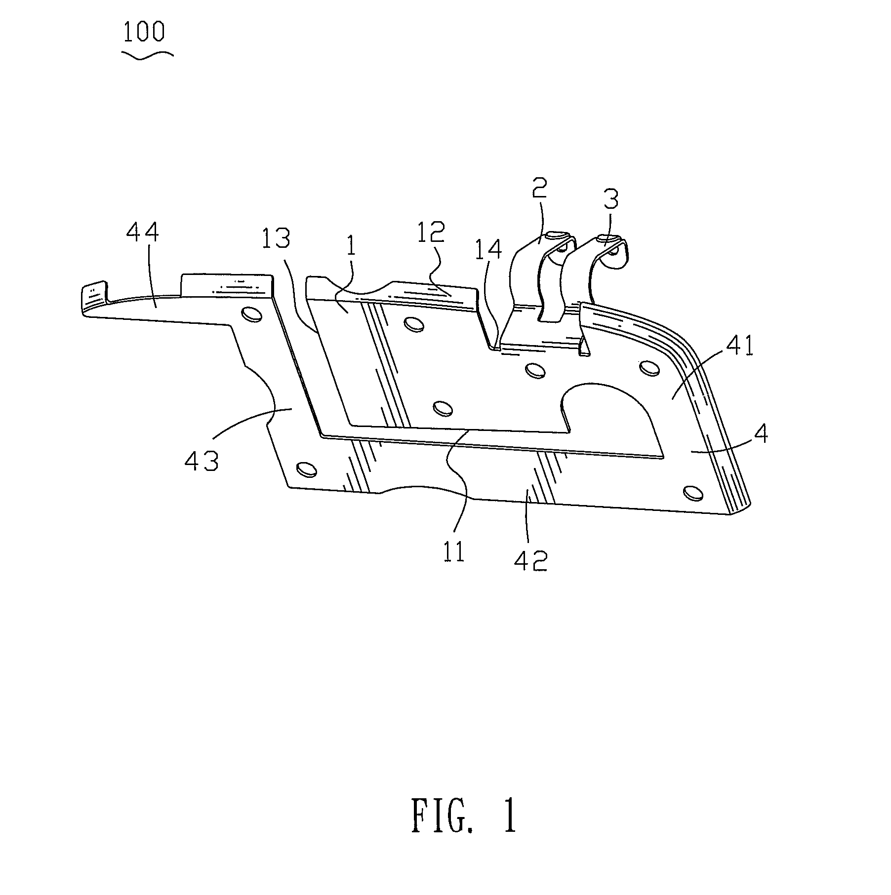
[0014]With reference to FIG. 1, a first embodiment of an antenna 100 according to the present invention is shown. The antenna 100 has a first radiating conductor 1. The first radiating conductor 1 is of a planar sheet and defines a first edge 11, a second edge 12 opposite to the first edge 11 and a lateral edge 13 connecting the first edge 11 and the second edge 12. The second edge 12 defines a notch 14. A feeding portion 2 and a grounding portion 3 extend outwardly from a bottom side of the notch 14 to show hook-shape.

[0015]Please refer to FIG. 1, the first radiating conductor 1 is connected to a second radiating conductor 4 which has a first connecting portion 41 extending outwardly from an upper portion of an end of the first radiating conductor 1 opposite to the lateral edge 13 and bending toward the first edge 11. A free end of the first connecting portion 41 bends towards the first radiating conductor 1 and extends to form a main body 42. The main body 42 is parallel to the fi...


PUM


Abstract

An antenna includes a first radiating conductor and a second radiating conductor. The first radiating conductor defines a first edge, a second edge and a lateral edge connecting the first edge and the second edge. The second radiating conductor has a main body spaced away from the second edge and connected to an end of the first radiating conductor far away from the lateral edge by a first connecting portion and extending towards the lateral edge. A free end of the main body bends to the second edge to form a second connecting portion spaced away from the lateral edge. A radiating end bends oppositely to the first radiating conductor from an end of the second connecting portion and is adjacent to the second edge. A feeding conductor and a grounding conductor are connected to an edge of the first radiating conductor different from the first edge and the lateral edge.

Description

BACKGROUND OF THE INVENTION[0001]1. Field of the Invention[0002]The present invention relates to an antenna, and more particularly to an antenna with anti-interference characteristic for use in a portable electrical device.[0003]2. The Related Art[0004]With the rapid development of wireless communication technologies, portable electrical devices used in wireless communication, such as mobile phone, wireless personal digital assistant (PDA) and laptop computer, are developed and produced, and antennas employed in the respective portable electrical devices are main parts to give influence to the wireless communication performance of the portable electrical devices, especially in the portable electrical devices with small volume yet multifunction.[0005]However, since a conventional antenna is mounted in a small space of a portable electrical device, the conventional antenna increases the vulnerability to the electromagnetic interference from the ambient environment, that is, the conven...

Claims


Application Information

Patent Timeline
Patent Type & Authority Patents(United States)
IPC IPC(8): H01Q1/24
CPCH01Q1/243H01Q5/371H01Q9/0421
Inventor YU, CHAO-HUICHEN, HUNG-JENWU, YU-YUANWANG, CHIH-KUO
Owner CHENG UEI PRECISION IND CO LTD
Why Eureka
Try Eureka