
Techniques for optimizing wireless communications via dynamic slew rate control of a wired communications channel

a wireless communication and dynamic slew rate technology, applied in the field of computer processing architectures, can solve the problems of interference with another communication channel, data transmitted over the wired communication channel may generate radiated emissions, frequency (rf) noise, etc., and achieve the effect of optimizing the reduction of interference and reducing high-frequency interference from the wired communication channel

Active Publication Date: 2022-06-09
NVIDIA CORP
View PDF10 Cites 0 Cited by
  • Summary
  • Abstract
  • Description
  • Claims
  • Application Information

AI Technical Summary

Benefits of technology

The patent text describes a technique that automatically selects a speed at which a wired communication channel can change to minimize interference with a nearby wireless communication channel. This selection is based on the characteristics of the wired and wireless channels and can change as those channels change. This results in reduced interference without affecting the data signals of the wired channel, leading to improved performance compared to previous approaches.

Problems solved by technology

However, under certain circumstances, one communications channel can interfere with another communications channel.
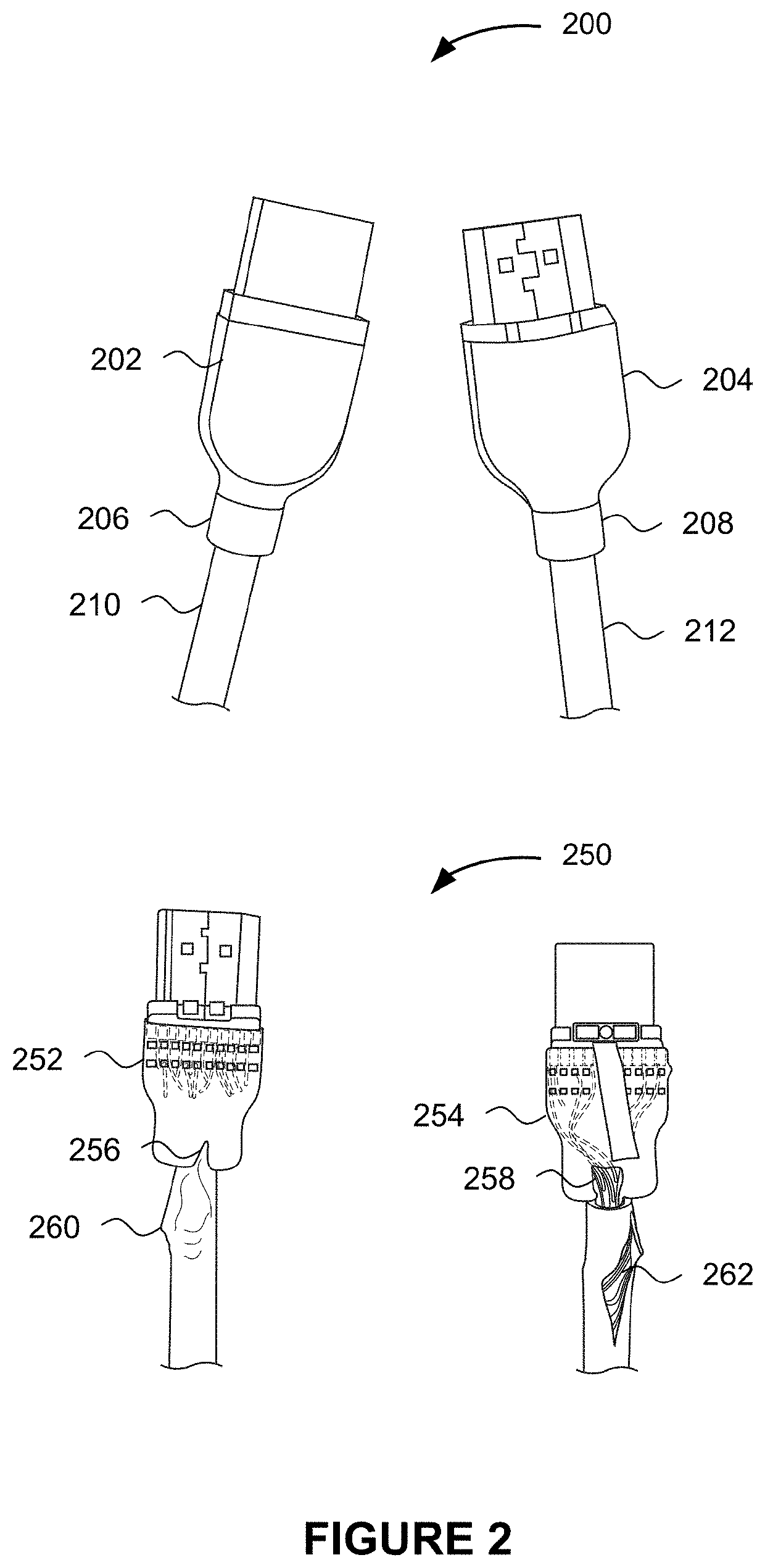
If the cable and / or connector associated with the wired communications channel is of poor construction or is damaged, then data transmitted over the wired communications channel may generate radiated emissions in the form of radio frequency (RF) noise that include frequency content in the range of the wireless communications channel.
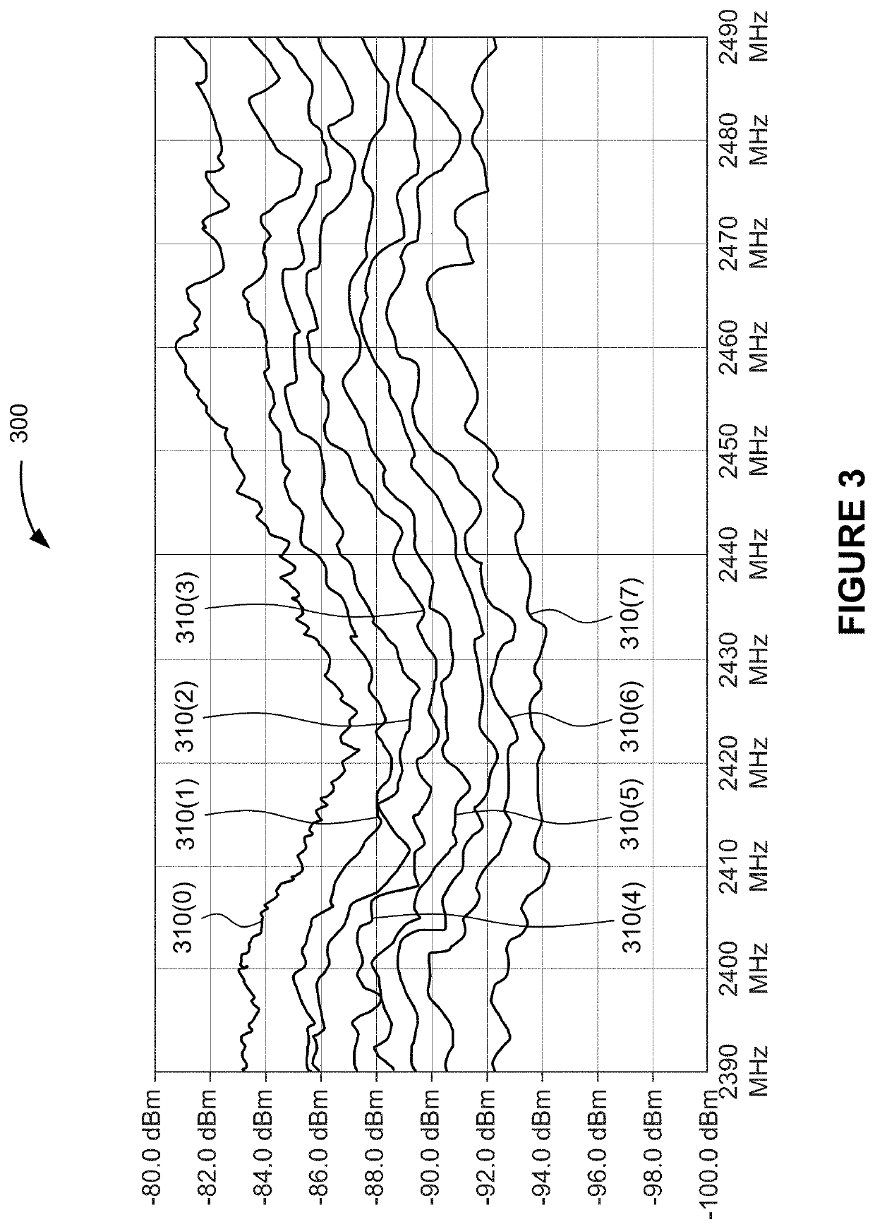
In particular, the rising edge and falling edge of signals transmitted over the wired communications channel often generate RF noise in frequency ranges typically employed by wireless communications channels.
As a result, the RF noise generated by the wired communications channel may interfere with data transmitted over the wireless communications channel.
For example, if the data rate of the data transmitted over the cable is 6 gigabits per second (Gbps), then a poorly constructed or damaged cable may generate RF noise in the range of 6 gigahertz (GHz).
If the wireless communications channel operates in the 6 GHz frequency range, then the 6 GHz RF noise generated by the poorly constructed or damaged cable may interfere with data transmitted over the 6 GHz wireless communications channel.
Such interference results in desensitizing the receiver of signals via the wireless communications channel, referred to herein as desense.
Under more extreme circumstances, the data may be corrupted or lost, such that the receiving computer-based system may not be able to receive the originally transmitted data.
One drawback with this technique is that the wired communications channel may support various modes, such as 1080p video, 1080i video, 720p video, 4 k HD video, 8 k HD video, Universal Serial Bus (USB) 3.1, and / or the like.
A low-pass filter that sufficiently suppresses high-frequency content for a first mode may cause signal distortion of the data content associated with a second mode.
Further, a low-pass filter optimized to suppress high-frequency content for a first wireless communications channel associated with a first frequency range may not be optimized to suppress high-frequency content for a second wireless communications channel associated with a second frequency range.
One drawback with this technique is that a slew rate that sufficiently suppresses high-frequency content for a first mode may cause signal distortion of the data content associated with a second mode.
Further, a slew rate optimized to suppress high-frequency content for a first wireless communications channel associated with a first frequency range may not be optimized to suppress high-frequency content for a second wireless communications channel associated with a second frequency range.

Method used


Image

  • Techniques for optimizing wireless communications via dynamic slew rate control of a wired communications channel
  • Techniques for optimizing wireless communications via dynamic slew rate control of a wired communications channel
  • Techniques for optimizing wireless communications via dynamic slew rate control of a wired communications channel

Examples


Embodiment Construction

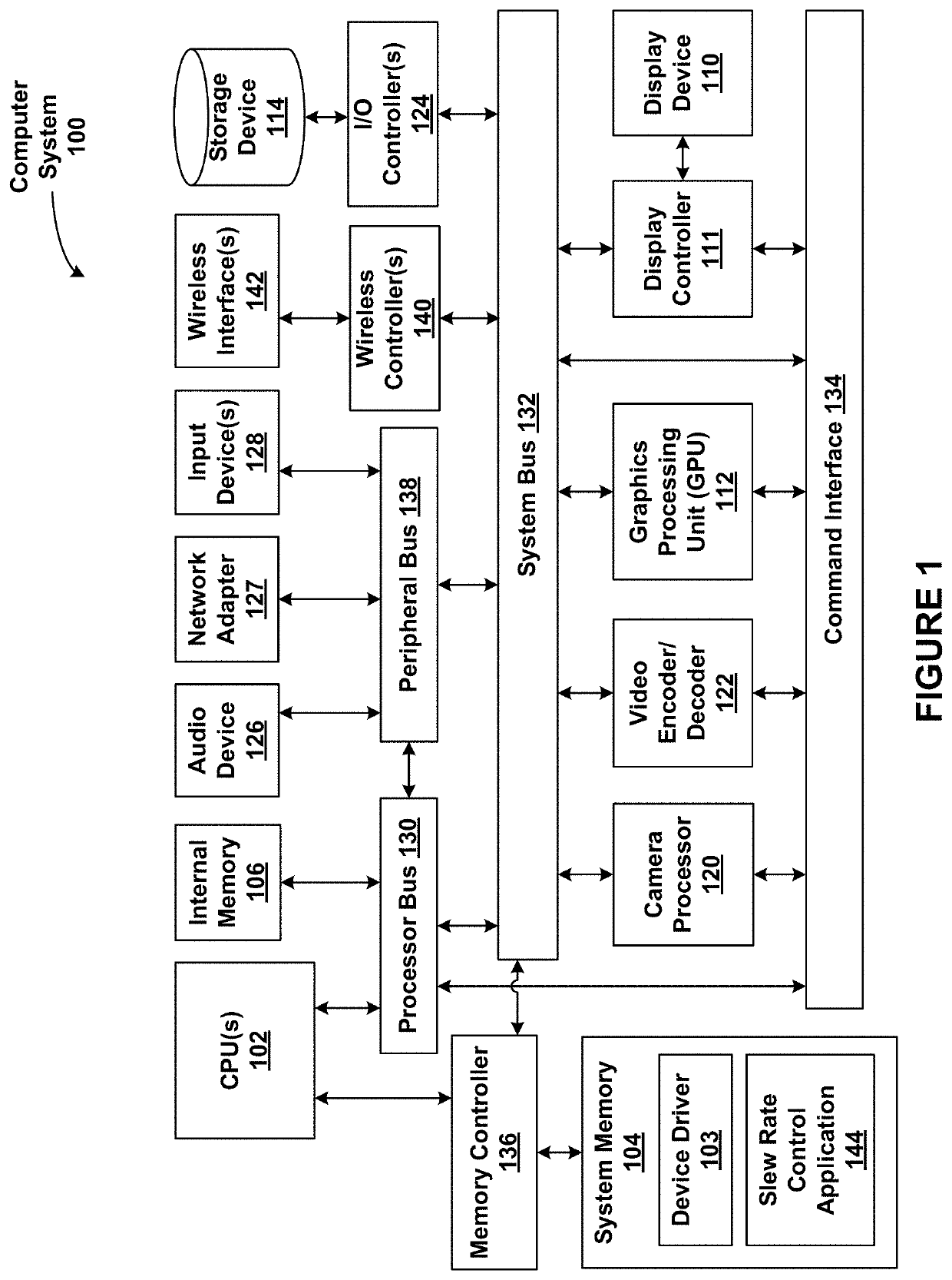
[0001]Various embodiments relate generally to computer processing architectures and, more specifically, to techniques for optimizing wireless communications via dynamic slew rate control of a wired communications channel.

Description of the Related Art

[0002]Modern computer-based systems, such as, personal computers, set top boxes, gaming systems, laptop computers, and / or the like, typically include multiple wired and wireless communications channels. Such computer-based systems transmit data to and receive data from, other computer-based systems via these wired and wireless communications channels. In general, different communications channels are designed to not interfere with each other. In that regard, different wireless communications channels may operate in different frequency bands. As a result, data exchanged between computer-based systems via one communications channel operating in one frequency band do not interfere with data exchanged between computer-based systems via anot...


PUM


Abstract

Various embodiments include techniques for reducing high-frequency interference to a wireless communications channel emanating from a wired communications channel. The techniques are directed towards an application that determines a mode of a particular wired communications channel. The mode of the wired communications channel is indicative of the frequency ranges at which the interference is generated. The application further determines a frequency and / or bandwidth of the wireless communications channel. The application selects a slew rate that reduces the high frequency interference from the wired communications channel at the frequency and / or bandwidth of the wireless communications channel. The application thereby optimizes the reduction of the high-frequency interference from the particular wired communications channel to the particular wireless communications channel.

Description

BACKGROUNDField of the Various Embodiments[0001]Various embodiments relate generally to computer processing architectures and, more specifically, to techniques for optimizing wireless communications via dynamic slew rate control of a wired communications channel.Description of the Related Art[0002]Modern computer-based systems, such as, personal computers, set top boxes, gaming systems, laptop computers, and / or the like, typically include multiple wired and wireless communications channels. Such computer-based systems transmit data to and receive data from, other computer-based systems via these wired and wireless communications channels. In general, different communications channels are designed to not interfere with each other. In that regard, different wireless communications channels may operate in different frequency bands. As a result, data exchanged between computer-based systems via one communications channel operating in one frequency band do not interfere with data exchang...

Claims


Application Information

Patent Timeline
Patent Type & Authority Applications(United States)
IPC IPC(8): H04L12/815
CPCH04L47/22H04L25/085H04W24/02H04L2012/2841H04W84/14H04W92/10H04M1/6091H04L63/02
Inventor BHUPATIRAJU, SRIRAMAGAVILAN, JOSELITOSTOYNOV, KIRIL
Owner NVIDIA CORP
Learn More