Method and apparatus for increasing heat radiation from an x-ray tube target shaft

a technology of x-ray tubes and target shafts, applied in the field of x-ray tubes, can solve the problems of limited enhancement or improvement of the overall average power capability of x-ray tubes, high peak temperatures occurring in the target assembly, and limited life and reliability issues with respect to the targ

Inactive Publication Date: 2010-01-05
GENERAL ELECTRIC CO
View PDF7 Cites 7 Cited by
  • Summary
  • Abstract
  • Description
  • Claims
  • Application Information

AI Technical Summary

Problems solved by technology

Higher peak power, though, results in higher peak temperatures occurring in the target assembly, particularly at the target “track,” or the point of impact on the target.
Thus, for increased peak power applied, there are life and reliability issues with respect to the target.
And, although spinning the target faster may reduce the peak focal track temperature, there is limited enhancement or improvement in the overall average power capability of the x-ray tube.

Method used


Image

  • Method and apparatus for increasing heat radiation from an x-ray tube target shaft
  • Method and apparatus for increasing heat radiation from an x-ray tube target shaft
  • Method and apparatus for increasing heat radiation from an x-ray tube target shaft

Examples


Embodiment Construction

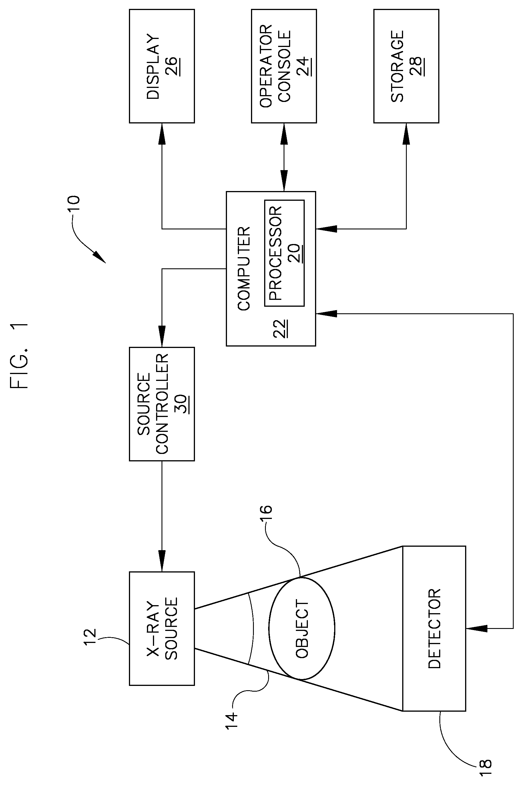
[0016]FIG. 1 is a block diagram of an embodiment of an imaging system 10 designed both to acquire original image data and to process the image data for display and / or analysis in accordance with the present invention. It will be appreciated by those skilled in the art that the present invention is applicable to numerous medical imaging systems implementing an x-ray tube, such as x-ray or mammography systems. Other imaging systems such as computed tomography systems and digital radiography systems, which acquire image three dimensional data for a volume, also benefit from the present invention. The following discussion of x-ray system 10 is merely an example of one such implementation and is not intended to be limiting in terms of modality.

[0017]As shown in FIG. 1, x-ray system 10 includes an x-ray source 12 configured to project a beam of x-rays 14 through an object 16. Object 16 may include a human subject, pieces of baggage, or other objects desired to be scanned. X-ray source 12 ...


PUM


Abstract

A target for generating x-rays includes a target substrate, a target shaft attached to the target substrate, and a radiation emissive coating applied to at least one of the target substrate and the target shaft, wherein a center-of-gravity of the target is positioned between a front bearing assembly and a rear bearing assembly of an x-ray tube.

Description

BACKGROUND OF THE INVENTION[0001]The present invention relates generally to x-ray tubes and, more particularly, to a high emissive coating on a target shaft of an x-ray tube.[0002]X-ray systems typically include an x-ray tube, a detector, and a bearing assembly to support the x-ray tube and the detector. In operation, an imaging table, on which an object is positioned, is located between the x-ray tube and the detector. The x-ray tube typically emits radiation, such as x-rays, toward the object. The radiation typically passes through the object on the imaging table and impinges on the detector. As radiation passes through the object, internal structures of the object cause spatial variances in the radiation received at the detector. The detector then emits data received, and the system translates the radiation variances into an image, which may be used to evaluate the internal structure of the object. One skilled in the art will recognize that the object may include, but is not limi...

Claims


Application Information

Patent Timeline
Patent Type & Authority Patents(United States)
IPC IPC(8): H01J35/00
CPCH01J35/105H01J2235/1204H01J2235/1208H01J2235/1229H01J35/107
Inventor HEBERT, MICHAELSTEINLAGE, GREGORY ALANTIEARNEY, JR., THOMAS C.
Owner GENERAL ELECTRIC CO
Why Eureka
Try Eureka