Method for scanning a surface with the aid of a coordinate measuring machine and coordinate measuring machine

a technology of coordinate measuring machine and surface scanning, which is applied in the direction of mechanical measuring arrangement, measurement device, instruments, etc., can solve the problems of even more complex relations, and achieve the effect of saving computational costs

Active Publication Date: 2010-01-12
CARL ZEISS IND MESSTECHN GMBH
View PDF19 Cites 6 Cited by
  • Summary
  • Abstract
  • Description
  • Claims
  • Application Information

AI Technical Summary

Benefits of technology

[0008]It is accordingly an object of the invention to provide a method for scanning a surface with an aid of a coordinate measuring machine and a coordinate measuring machine which overcome the above-mentioned disadvantages of the prior art methods and devices of this general type, which permit the measuring period during scanning to be kept as short as possible. The aim in this case is to prevent measuring errors and to take account of measuring arrangements in the case of which the coordinate measuring machine or the probe element has various maximum speed magnitudes with reference to various degrees of freedom of the movement. A maximum speed magnitude of a degree of freedom is understood to mean that in the case of a movement exclusively in the direction defined by the degree of freedom the associated maximum speed magnitude may not or cannot be exceeded.
[0016]The inventive method has the advantage that it is not the degree of freedom with the lowest maximum speed magnitude that automatically determines the maximum magnitude of the scanning speed. Rather, it can be determined for a specifically prescribed estimated scanning path whether a higher scanning speed is possible and whether the magnitude of the scanning speed can nevertheless be kept constant over the entire scanning path. Moreover, it is possible to select another scanning path or (for example, by changed orientation and / or positioning of the work piece relative to the coordinate measuring machine) to arrange a scanning path of given shape in a different way in the measuring range. The maximum magnitude of the scanning speed can be higher in the case of this other arrangement. In particular, it is possible on the basis of the results of the inventive method for a given shape of a scanning path to arrange the scanning path such that the highest possible maximum magnitude of the scanning speed is attained for all possible arrangements. This is of particular advantage especially when identically configured work pieces are to be measured by the coordinate measuring machine over and over in the course of mass production of work pieces.
[0022]The preferred embodiment is based on the idea that it is necessary to consider only the extreme points for fixing or determining the maximum magnitude of the scanning speed. In this case, even the evaluation of a portion of the extreme points can suffice, for example, when the scanning path is a circular track. Thus, it is unnecessary, in particular, to evaluate the speed components (the term “component” relates to an assigned coordinate axis) for each point on the scanning path as to whether the speed component is greater than the maximum speed magnitude of the associated degree of freedom or the associated coordinate axis. It is possible for this reason to make substantial savings on computational outlay, and forward planning of the measurement of a work piece can be carried out in an acceptable time.
[0027]When determining the maximum magnitude of the scanning speed, in particular, in order to take account of the extreme points, it is possible to calculate a tangent of the estimated scanning path that runs parallel to the linear axis. In other words, a straight line (the tangent) touches the scanning path (when at least only a local region is considered) at only one point, specifically the extreme point, that is to be taken into account. Here, as mentioned, the tangent is parallel to the linear axis or the coordinate axis of the coordinate whose maximum of the derivative of the magnitude of the coordinate is to be found with respect to the path. In specific cases, such as, for example, that of a circular track, the extreme points can be determined particularly easily by determining the point with the greatest distance and the point with the least distance from the respective coordinate axis.
[0031]The evaluation of the extreme points and the determination of the maximum magnitude of the scanning speed using the method for calculating the speed tangent vector are very easy. If the component is, for example, the X component of a Cartesian coordinate system, use is then made only of the X component of the tangent vector as evaluation component for an extreme point for which the derivative of the magnitude of the X-coordinate with respect to the scanning path is a maximum.

Problems solved by technology

The relationships become even more complex in this case when different maximum speed magnitudes are defined for all degrees of freedom of the movement.

Method used


Image

  • Method for scanning a surface with the aid of a coordinate measuring machine and coordinate measuring machine
  • Method for scanning a surface with the aid of a coordinate measuring machine and coordinate measuring machine
  • Method for scanning a surface with the aid of a coordinate measuring machine and coordinate measuring machine

Examples


Embodiment Construction

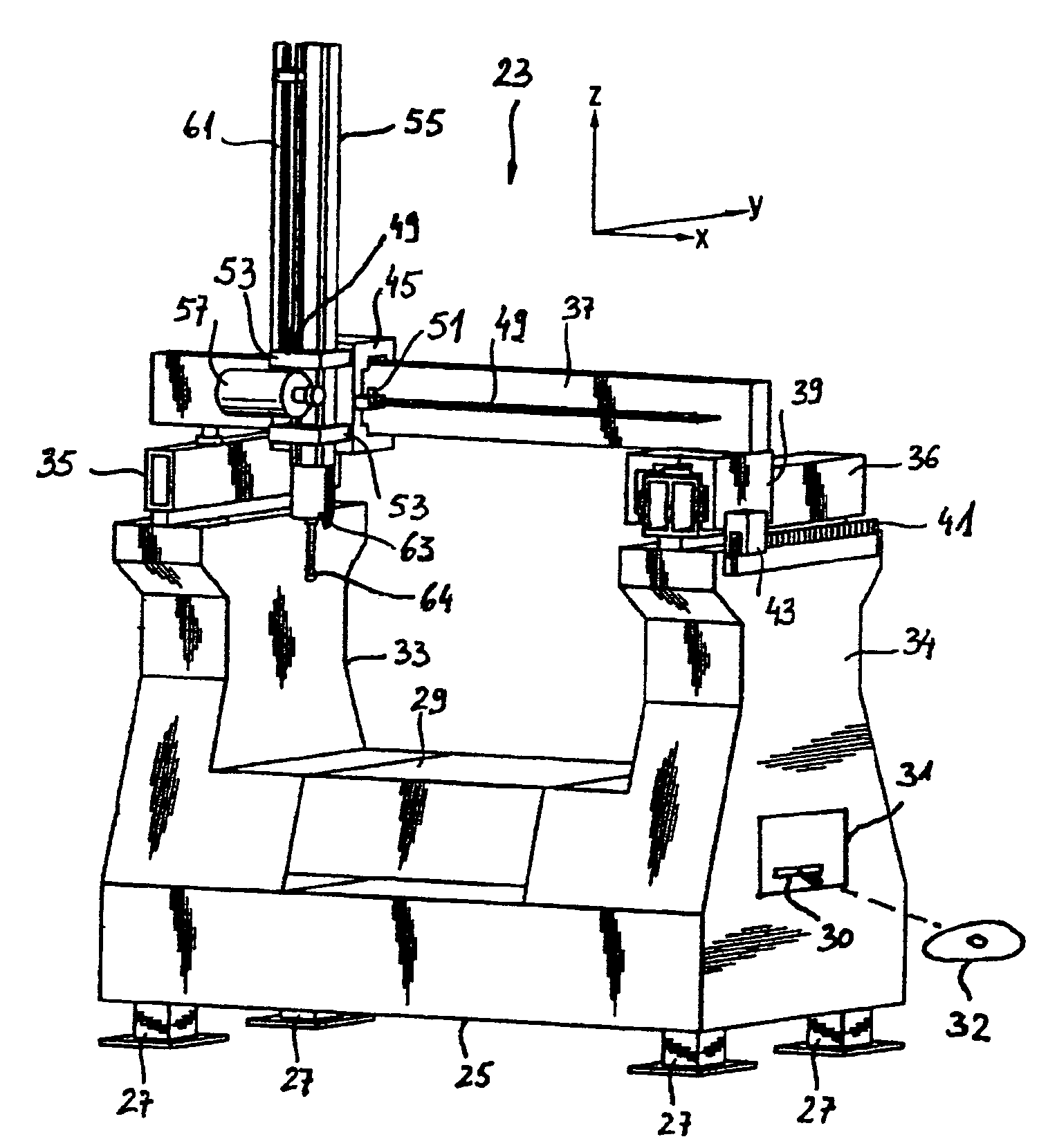
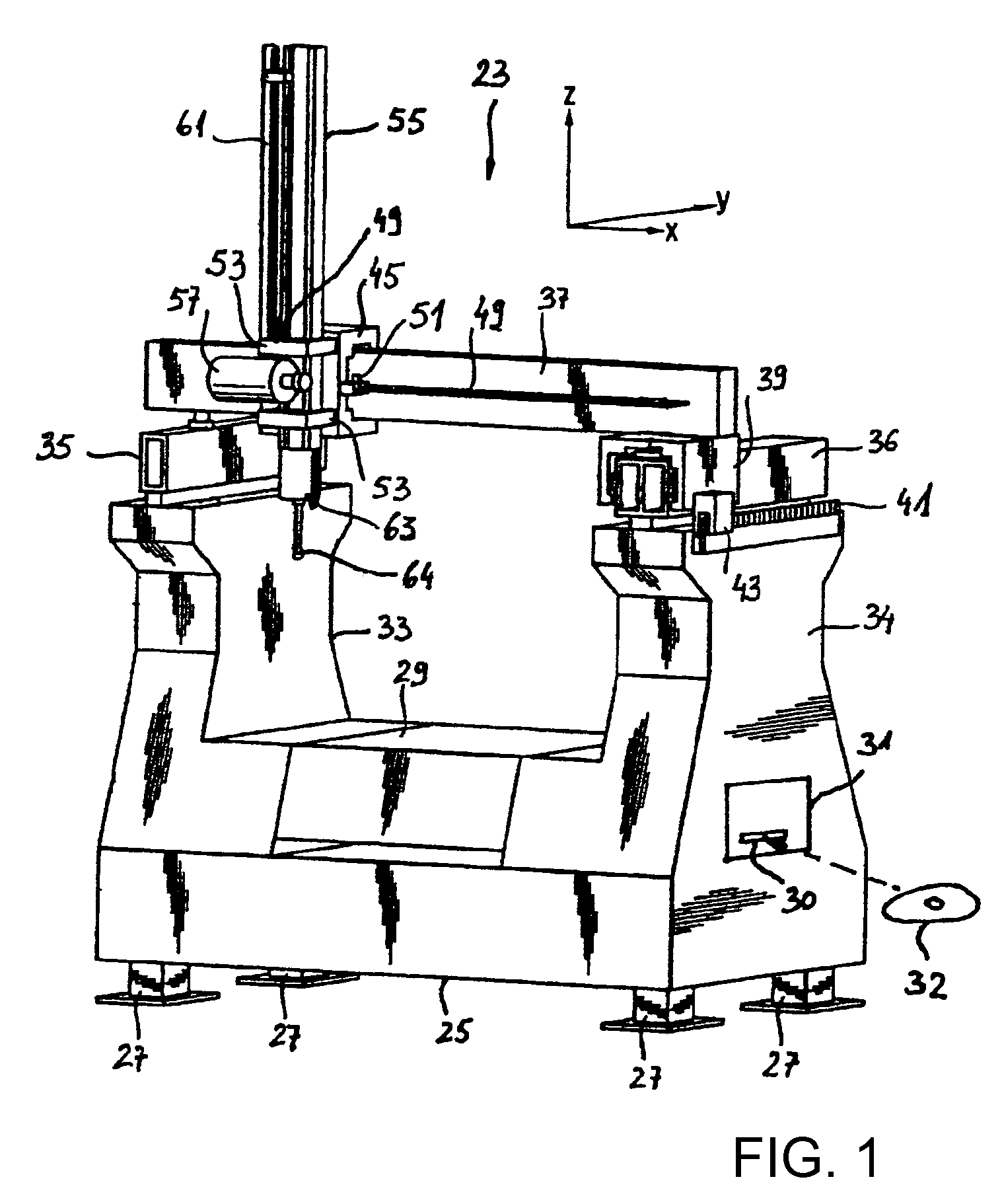
[0046]Referring now to the figures of the drawing in detail and first, particularly, to FIG. 1 thereof, there is shown an embodiment of an inventive coordinate measuring machine on an example of a coordinate measuring machine 23 of a gantry configuration.

[0047]The coordinate measuring machine has a base 25 with feet 27. In its middle, the base 25 has a work piece holder or work piece support 29 on which a work piece to be measured is to be arranged. Extending upward on either side of the work piece holder 29 on the base 25 are struts 33, 34 that carry longitudinal guides 35, 36 that are arranged on either side of the work piece holder 29 and extend parallel to one another in a horizontal direction (the Y-direction). Extending horizontally in a fashion orthogonal to the longitudinal guides 35, 36 is a transverse guide 37 in the X direction that is mounted on the longitudinal guides 35, 36 such that it can be displaced linearly in the Y direction. For this purpose, there is provided o...


PUM


Abstract

A method for scanning a work piece surface uses a coordinate measurement device. A probe element is brought into contact with the surface and the probe element is moved along the surface. The coordinate measurement device has a plurality of degrees of freedom, which are independent of one another, in the possible movements of the probe element with respect to the work piece. Maximum speeds which describe the maximum of a movement speed component of the probe element based on the respective degree of freedom are defined for the degrees of freedom. An estimated path on which the probe element is intended to move during scanning is predefined. The actual scanning path can differ from the estimated scanning path. A maximum scanning speed at which the estimated scanning path can be traveled with a constant speed of the probe element is determined.

Description

CROSS-REFERENCE TO RELATED APPLICATION[0001]This is a continuing application, under 35 U.S.C. § 120, of copending international application No. PCT / EP2007 / 003724, filed Apr. 19, 2007, which designated the United States; this application also claims the priority, under 35 U.S.C. § 119, of German patent application No. DE 10 2006 019 382.2, filed Apr. 24, 2006; the prior applications are herewith incorporated by reference in their entirety.BACKGROUND OF THE INVENTION[0002]The invention relates to a method for scanning a work piece surface with the aid of a coordinate measuring machine, and to a coordinate measuring machine that is configured, in particular to execute the method. The invention further contains a determining device for determining a value of a movement speed of the coordinate measuring machine.[0003]Coordinate measuring machines are used to measure coordinates of surface points of a work piece. For example, a conventional coordinate measuring machine has a work piece ho...

Claims


Application Information

Patent Timeline
Patent Type & Authority Patents(United States)
IPC IPC(8): G01B5/004
CPCG01B5/008G01B21/045
Inventor FUCHS, ANDREASBURGER, JOCHENDEEG, HERMANN
Owner CARL ZEISS IND MESSTECHN GMBH
Why Eureka
Try Eureka