[0008]It is accordingly an object of the invention to provide a method for scanning a surface with an aid of a coordinate measuring
machine and a coordinate measuring
machine which overcome the above-mentioned disadvantages of the prior art methods and devices of this general type, which permit the measuring period during scanning to be kept as short as possible. The aim in this case is to prevent measuring errors and to take account of measuring arrangements in the case of which the coordinate measuring machine or the probe element has various maximum speed magnitudes with reference to various degrees of freedom of the movement. A maximum speed magnitude of a degree of freedom is understood to mean that in the case of a movement exclusively in the direction defined by the degree of freedom the associated maximum speed magnitude may not or cannot be exceeded.
[0016]The inventive method has the
advantage that it is not the degree of freedom with the lowest maximum speed magnitude that automatically determines the
maximum magnitude of the scanning speed. Rather, it can be determined for a specifically prescribed estimated scanning path whether a higher scanning speed is possible and whether the magnitude of the scanning speed can nevertheless be kept constant over the entire scanning path. Moreover, it is possible to select another scanning path or (for example, by changed orientation and / or positioning of the work piece relative to the coordinate measuring machine) to arrange a scanning path of given shape in a different way in the measuring range. The
maximum magnitude of the scanning speed can be higher in the case of this other arrangement. In particular, it is possible on the basis of the results of the inventive method for a given shape of a scanning path to arrange the scanning path such that the highest possible
maximum magnitude of the scanning speed is attained for all possible arrangements. This is of particular
advantage especially when identically configured work pieces are to be measured by the coordinate measuring machine over and over in the course of
mass production of work pieces.
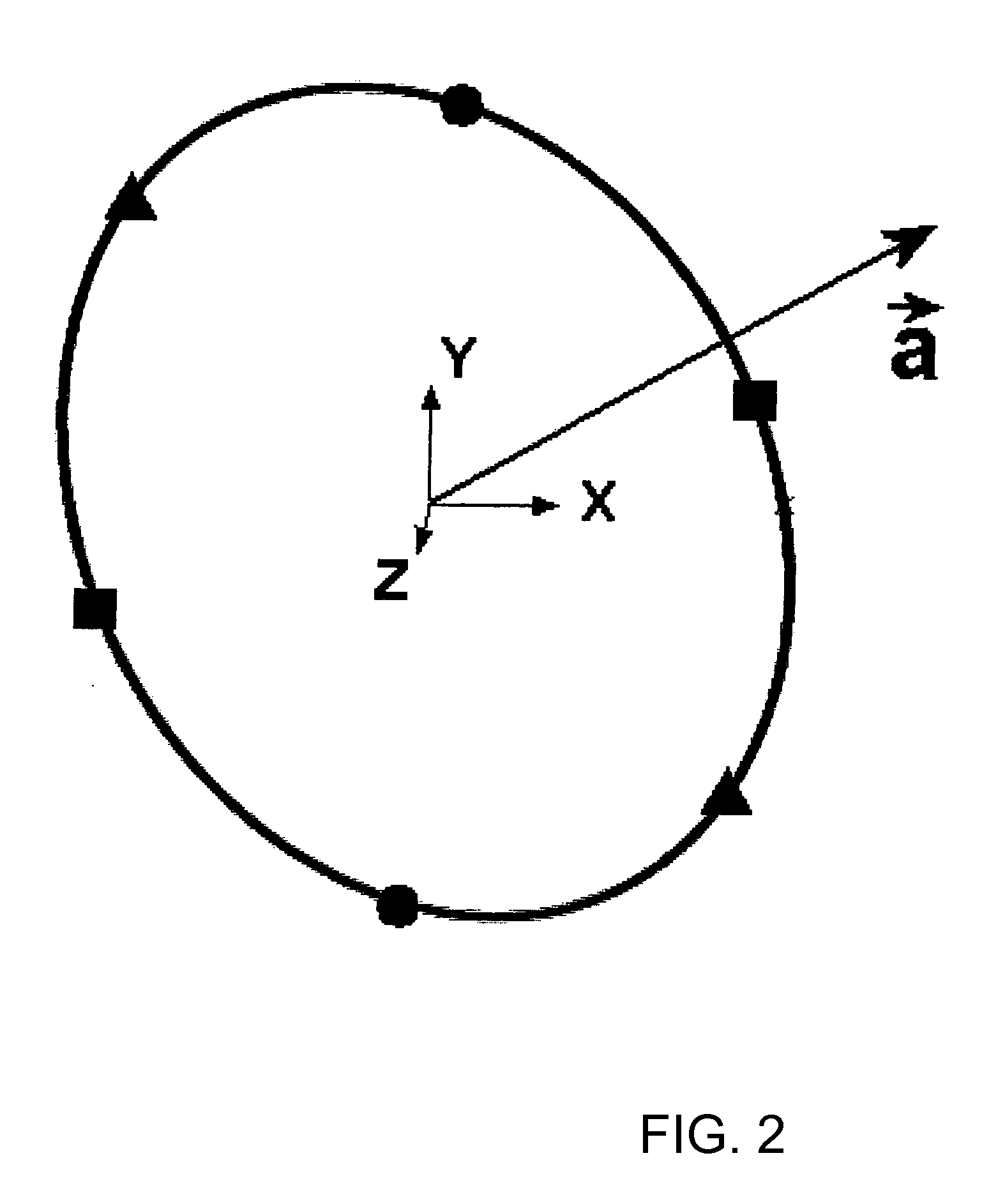
[0022]The preferred embodiment is based on the idea that it is necessary to consider only the extreme points for fixing or determining the maximum magnitude of the scanning speed. In this case, even the evaluation of a portion of the extreme points can suffice, for example, when the scanning path is a circular track. Thus, it is unnecessary, in particular, to evaluate the speed components (the term “component” relates to an assigned coordinate axis) for each point on the scanning path as to whether the speed component is greater than the maximum speed magnitude of the associated degree of freedom or the associated coordinate axis. It is possible for this reason to make substantial savings on computational outlay, and forward planning of the measurement of a work piece can be carried out in an acceptable time.
[0027]When determining the maximum magnitude of the scanning speed, in particular, in order to take account of the extreme points, it is possible to calculate a tangent of the estimated scanning path that runs parallel to the linear axis. In other words, a straight line (the tangent) touches the scanning path (when at least only a local region is considered) at only one point, specifically the extreme point, that is to be taken into account. Here, as mentioned, the tangent is parallel to the linear axis or the coordinate axis of the coordinate whose maximum of the derivative of the magnitude of the coordinate is to be found with respect to the path. In specific cases, such as, for example, that of a circular track, the extreme points can be determined particularly easily by determining the point with the greatest distance and the point with the least distance from the respective coordinate axis.
[0031]The evaluation of the extreme points and the determination of the maximum magnitude of the scanning speed using the method for calculating the speed tangent vector are very easy. If the component is, for example, the X component of a Cartesian coordinate
system, use is then made only of the X component of the tangent vector as evaluation component for an extreme point for which the derivative of the magnitude of the X-coordinate with respect to the scanning path is a maximum.

