Efficient dynamic stimulation in an implanted device

a dynamic stimulation and implanted device technology, applied in the field of pulse generators, to achieve the effects of reducing the energy dissipation of batteries, reducing the electrolysis effect at the electrodes, and saving energy

Active Publication Date: 2006-11-23
MEDTRONIC INC
View PDF24 Cites 43 Cited by
  • Summary
  • Abstract
  • Description
  • Claims
  • Application Information

AI Technical Summary

Benefits of technology

[0011] The charging circuitry is most preferably driven by an internal battery contained in the device. The charging circuitry, operated by a micro-controller, comprises a direct current (DC) charging circuit and an alternating current (AC) charging circuit which are each able to charge the stimulation capacitor by respective differential potentials. The micro-controller is able to minimize battery energy dissipation by using either or both circuits, and to set the time of use of each circuit in order to charge the stimulation capacitor to the initial operating voltage level. The AC circuit enables the operating voltage to be reached regardless of a voltage delivered by the battery. Similarly, for any adjusted operating voltage or other pulse parameter such as the pulse period, the micro-controller sets the time of use of each circuit so as to charge the stimulation capacitor to the adjusted operating voltage efficiently.
[0012] Parameters such as tissue impedance and operating voltage level are derived from measured potentials on the stimulation capacitor as it discharges. Thus, no current sensing mechanism, as is used by other tissue stimulators known in the art, is required in preferred embodiments of the present invention. Current sensing mechanisms, typically resistors, drain energy. Not implementing such a mechanism achieves a significant saving in energy supplied by a battery powering the stimulation device.
[0013] In some preferred embodiments of the present invention, a resistive element having a controlled resistance is coupled between the electrodes so as to be able to short-circuit an interface capacitance formed in the tissue being stimulated. The resistive element preferably comprises a field effect transistor (FET) having a gate which acts as a control electrode for the resistive element, the gate being activated by a control signal from the micro-controller. By short-circuiting the electrodes and the interface capacitance at times chosen by the micro-controller, electrolysis effects at the electrodes may be reduced and even eliminated, and the tissue stimulation level may be more precisely defined.

Problems solved by technology

Such excitation is typically an undesired side effect of the tissue stimulation, and methods to reduce or eliminate the effect have been sought.

Method used


Image

  • Efficient dynamic stimulation in an implanted device
  • Efficient dynamic stimulation in an implanted device
  • Efficient dynamic stimulation in an implanted device

Examples


Embodiment Construction

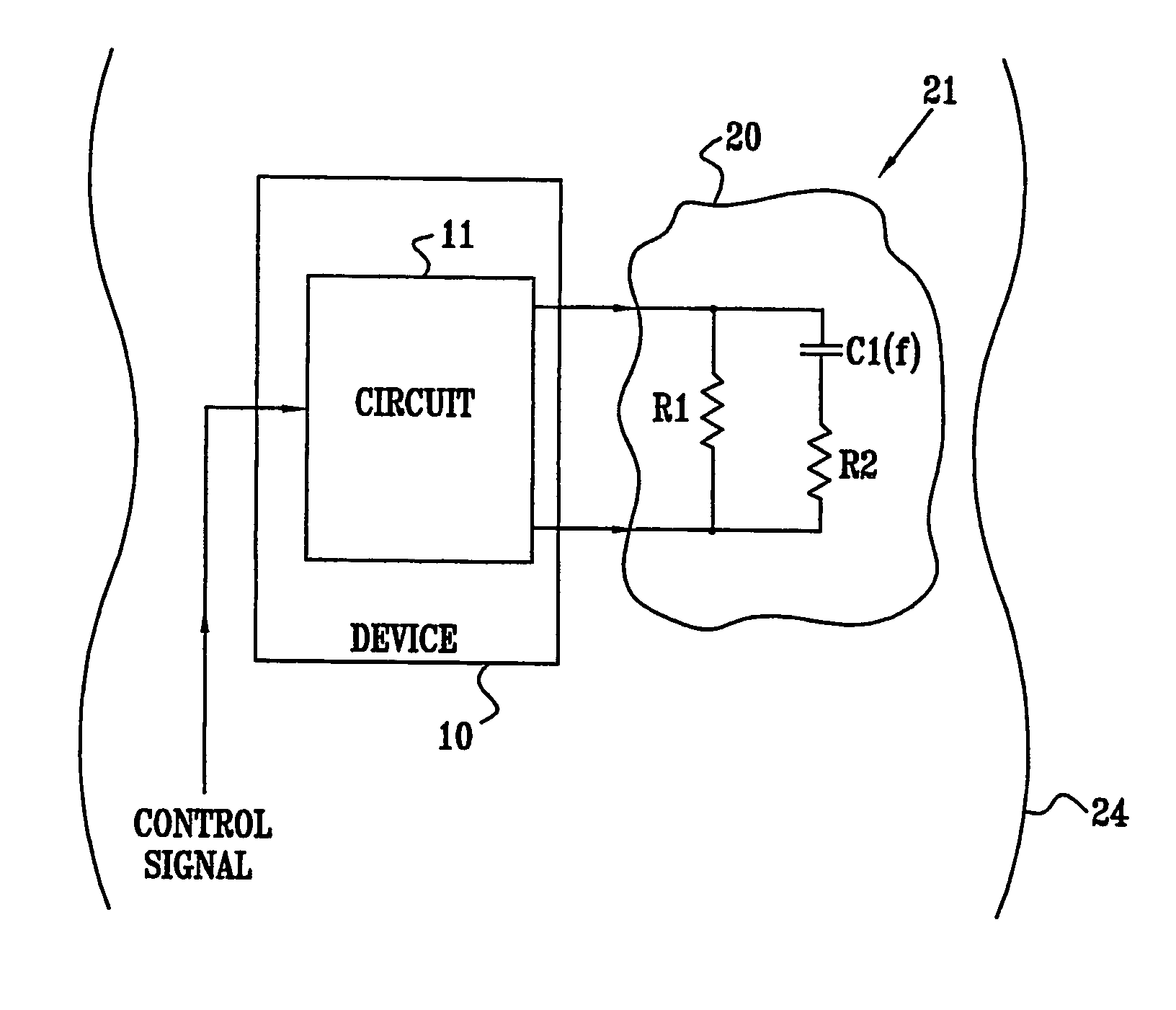
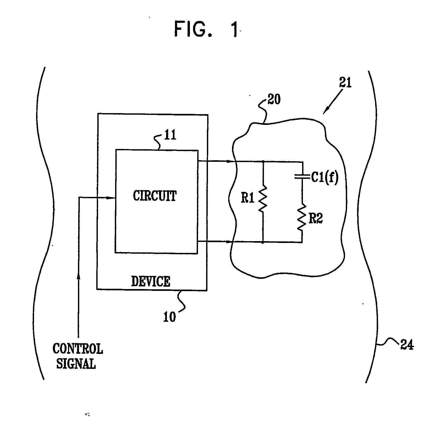
[0165] Reference is now made to FIG. 1, which is a schematic diagram illustrating a stimulation device 10, according to a preferred embodiment of the present invention. Device 10 comprises a circuit 11 which is used to generate electrical waveforms, the waveforms in turn stimulating tissue 20 of a subject 24. Preferably, tissue 20 comprises a muscle, most preferably a sphincter muscle, or a nerve of the subject, although it will be appreciated that tissue 20 may comprise any tissue of subject 24. Device 10 is preferably implanted in the subject, and after implantation and adjustment, is most preferably operated by a control signal generated by subject 24 and input to circuit 11. Circuit 11 may be implemented as discrete components, or as a custom-built component such as an application specific integrated circuit (ASIC), or as a combination of discrete and custom-built components. By way of example, the description hereinbelow applies when circuit 11 comprises discrete components.

[0...


PUM


Abstract

A method for measuring impedance of a tissue (20), consisting of charging a capacitor (C15) to a potential, and discharging the capacitor for a discharge period through the tissue. The method further consists of measuring a voltage drop on the capacitor over the discharge period and determining the impedance of the tissue responsive to the potential, the voltage drop, and the discharge period.

Description

CROSS-REFERENCE TO RELATED APPLICATION [0001] This application claims the benefit of U.S. Provisional Patent Application 60 / 432,932, filed Dec. 12, 2002, which is incorporated herein by reference.FIELD OF THE INVENTION [0002] The present invention relates generally to electrical pulse generators, and specifically to pulse generators for electrical stimulation of tissue. BACKGROUND OF THE INVENTION [0003] Stimulation of tissue of a subject by applying an electrical potential to the tissue is well known in the medical art. Herein, in the specification and in the claims, tissue is to be understood as comprising muscle and / or nerve of a subject. Levels and type of stimulation used depend on a number of factors, such as whether the stimulation is applied externally, and the desired effect of the stimulation. When the tissue is stimulated directly, by one or more electrodes implanted in the tissue, levels of stimulation needed to achieve a specific desired effect are typically orders of m...

Claims


Application Information

Patent Timeline
Patent Type & Authority Applications(United States)
IPC IPC(8): A61N1/18A61B5/05A61NA61N1/365
CPCA61N1/36521A61N1/36142A61N1/3716A61N1/37
Inventor VAINGAST, SHAICOHEN, EHUD
Owner MEDTRONIC INC
Why Eureka
Try Eureka