Operating lever device

a lever and lever technology, applied in the direction of mechanical control devices, instruments, shock absorbers, etc., can solve the problems of difficult selection of one of the plurality of rotary dampers, inability to adjust the and inability to carry out replacement operations easily, so as to achieve increased or reduced resistance force of the rotary damper means to the operating lever, the effect of increasing or reducing the resistance for

Inactive Publication Date: 2010-01-12
KOMATSU LTD
View PDF8 Cites 1 Cited by
  • Summary
  • Abstract
  • Description
  • Claims
  • Application Information

AI Technical Summary

Benefits of technology

[0015]According to the present invention, the rotation center of the rotary damper means which applies the resistance force to the operating lever at the time of the inclining operation of the operating lever is deviated from the rotation center of the shaft. With this configuration, the resistance force of the rotary damper means to the operating lever can be increased or reduced by proportionating a value obtained by dividing a distance from the rotation center of the shaft to the fixing pin by a distance from the rotation center of the rotary damper means to the fixing pin.
[0016]Even if the same rotary damper means are used, the mounting position of the rotary damper means on the shaft can be changed, and the resistance force to be applied from the rotary damper means to the operating lever can be increased or reduced.
[0017]According to the present invention, by deviating the rotation center of the rotary damper means from the rotation center of the shaft, a greater resistance force or a smaller resistance force as compared with the conventional rotary damper can be applied to the operating lever. By changing the mounting position of the rotary damper means with respect to the shaft, the ratio of deviating the rotation center of the rotary damper means from the rotation center of the shaft can be changed, and the resistance force to be applied from the rotary damper means to the operating lever can variably be adjusted. With this configuration, a resistance force suitable for the sensibility of an operator can freely be adjusted by changing the mounting position of the rotary damper means with respect to the shaft.
[0018]The hooking position between the fixing pin and the damper lever can be adjusted. By changing the hooking position, the distance from the rotation center of the shaft to the fixing pin and the distance from the rotation center of the rotary damper means to the fixing pin can be changed, a value obtained by dividing a distance from the rotation center of the shaft to the fixing pin by a distance from the rotation center of the rotary damper means to the fixing pin can be changed. With this, the resistance force of the rotary damper means against the operating lever can be increased or reduced.
[0019]The fixing pin can be disposed on any position around the rotation shaft of the shaft. A freedom degree of design for disposing the rotary damper means of the operating lever device can be enhanced.
[0020]The operating lever may be mounted on the shaft, or the shaft and the operating lever may be integrally formed together. Thus, the shaft support body also has a function as a lever support body which rotatably supports the operating lever.

Problems solved by technology

Due to this configuration, it is not possible to adjust the resistance force from the rotary damper 52 with respect to the inclining operation of the operating lever 54 in accordance with sensibility of the operator.
Even in this case, the rotary dampers must be replaced after the operating lever is detached, and the replacement operation can not be carried out easily.
It is also difficult to select one of the plurality of rotary dampers that is most suitable for the operator's sensibility.

Method used


Image

  • Operating lever device
  • Operating lever device
  • Operating lever device

Examples


first embodiment

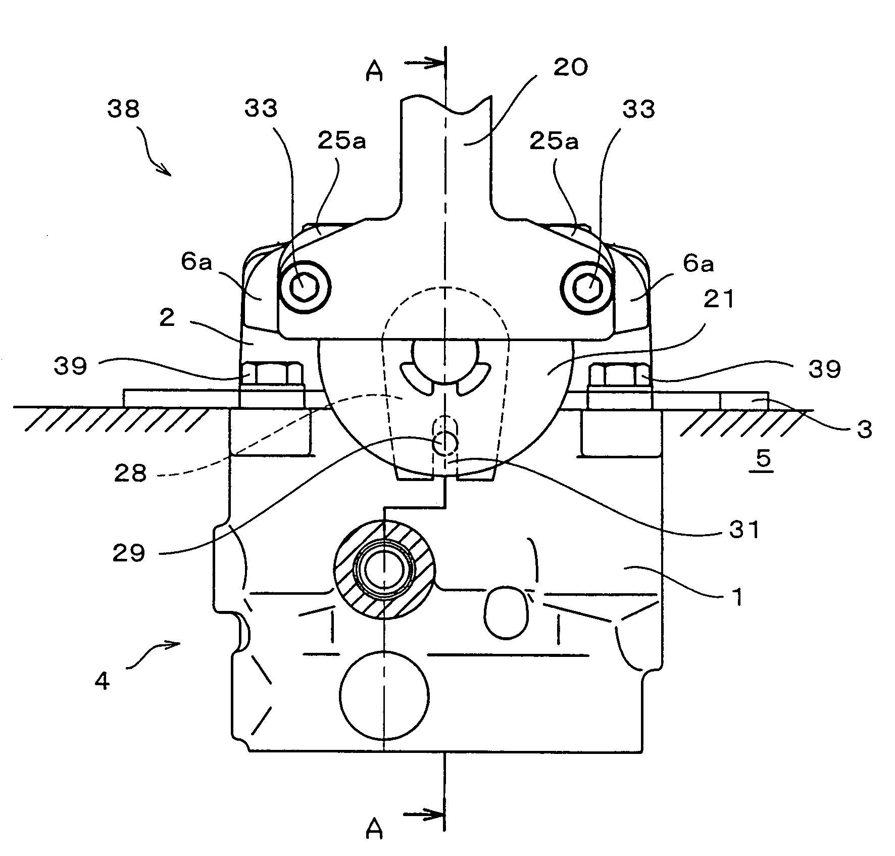
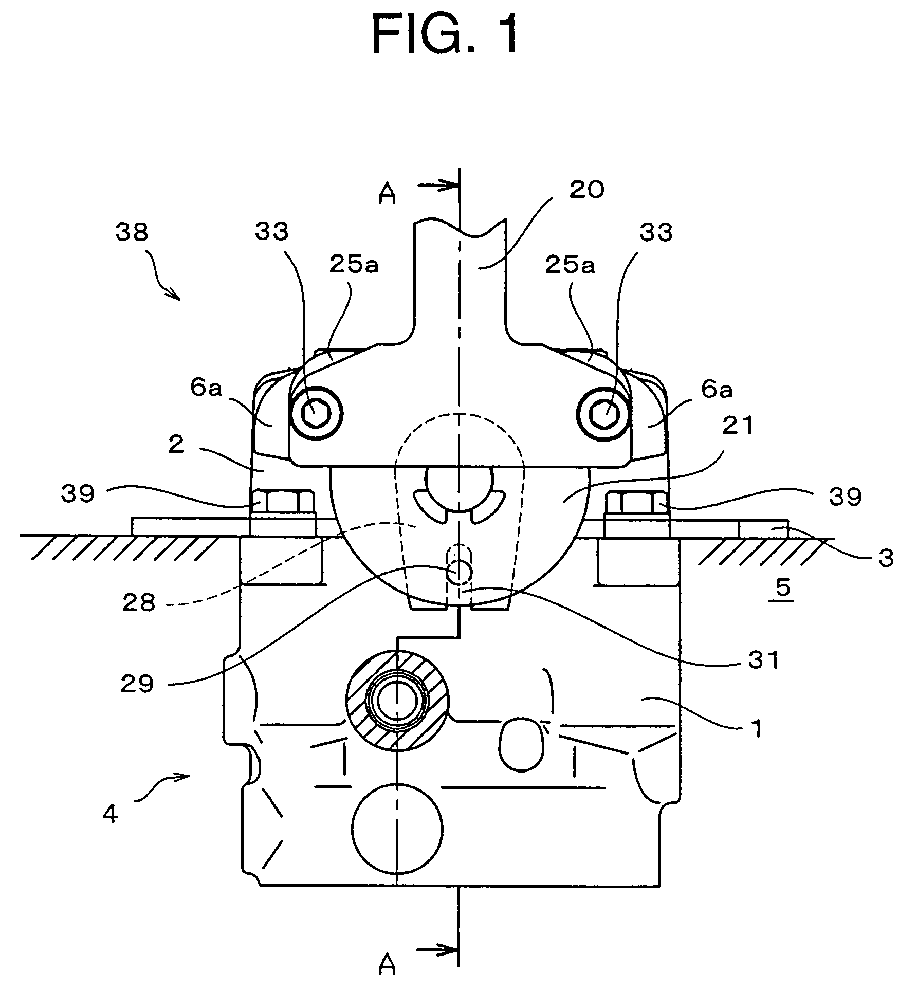
[0035]As shown in FIG. 1, an operating lever device 38 is provided on a floor 5 of a driver's room or the like in construction machinery. The operating lever device 38 is fixed on the floor 5 through a plate 3 by bolts 39. As shown in FIGS. 2 and 4, the operating lever device 38 comprises a pair of left and right operating levers 20 and 20′, a pair of left and right rotary damper means 21 and 21′, a pair of left and right shafts 6 and 6′, a pair of left and right flange portions 6a and 6′a formed on the shafts 6 and 6′, and a shaft support body 2 rotatably supporting the shafts 6 and 6′. The shaft support body 2 is mounted on a body 1 through fixing bolts 36, and a valve body 4 is accommodated in the body 1.

[0036]The operating levers 20 and 20′, the rotary damper means 21 and 21′, the shafts 6 and 6′ and the flange portions 6a and 6′a are the pair of left and right sets. The members in each set carry out the same operation by an inclining operation of the operating lever 20 or the o...

second embodiment

[0074]FIG. 7 shows second embodiment of the present invention. The second embodiment is the same structure as the first embodiment except that the fixing pin 29 is located above the shaft 6. The effect as the operating lever device of the second embodiment is also the same as that of the operating lever device of the first embodiment. Therefore, in the second embodiment, the same members as those of the first embodiment are used, and explanation of the member will be omitted. A structure of the second embodiment that is different from the first embodiment will mainly be explained below.

[0075]As shown in FIG. 7, fixing pins 29 and 29′ are disposed above the shafts 6 and 6′. Since the fixing pins 29 and 29′ are disposed above the shafts 6 and 6′, the long grooves 31 of the damper levers 28 and 28′ are disposed to be directed upward.

[0076]With this configuration, the fixing pins 29 and 29′ can be exposed from the floor on which the operating lever device is mounted. Further, the mounti...


PUM


Abstract

A rotor and a seat mounted on a first shell is disposed between an annular first shell and an annular second shell both constituting a damper case, thereby forming a rotary damper device. A damper lever on which the rotor is mounted is hooked on a fixing pin fixed to a body. Viscous fluid such as highly viscous oil is charged into a damper chamber formed between the rotor and the seat, and a viscous resistance is applied to the rotor and the seat. In a state in which a rotation center of the rotary damper device is deviated from a rotation center of the shaft which is rotated by the operating lever, the damper case is fixed to a flange portion of the shaft, the rotor and the seat are allowed to rotate relatively to each other by an inclining operation of the operating lever, and a resistance force from the rotary damper device is applied to the operating lever.

Description

TECHNICAL FIELD[0001]The present invention relates to an operating lever device which is suitable for switching and operating a direction-switching valve and the like disposed in an oil hydraulic circuit used for, for example, construction equipment and industrial equipment.BACKGROUND ART[0002]Generally, in the construction equipment or the industrial equipment, a hydraulic cylinder and the like used for operation are disposed, in addition, hydraulic motors are disposed on left and right sides of a lower running body, and the hydraulic motors are used as driving motors. According to the driving motor, pressurized oil is supplied from an oil pressure source or pressurized oil from the driving motor is discharged by controlling a driving direction-control valve. With this configuration, it is possible to control the running state of the lower running body on a road.[0003]The construction machinery or the industrial machinery is provided with a cab for defining a driver's room in a fra...

Claims


Application Information

Patent Timeline
Patent Type & Authority Patents(United States)
IPC IPC(8): G05G1/04E02F9/20F15B13/042F15B13/14F16F9/54G05G5/03
CPCE02F9/2004F15B13/0422G05G1/04G05G5/03F15B13/14Y10T74/20582
Inventor MOTOTANI, MASAYOSHIHORI, SHUUJIKOZUKA, DAISUKESATO, YASUHIROMIYAKE, KOICHI
Owner KOMATSU LTD
Why Eureka
Try Eureka