

Artificial joint
- Summary
- Abstract
- Description
- Claims
- Application Information
AI Technical Summary
Benefits of technology
Problems solved by technology
Method used
Image

Examples
first embodiment
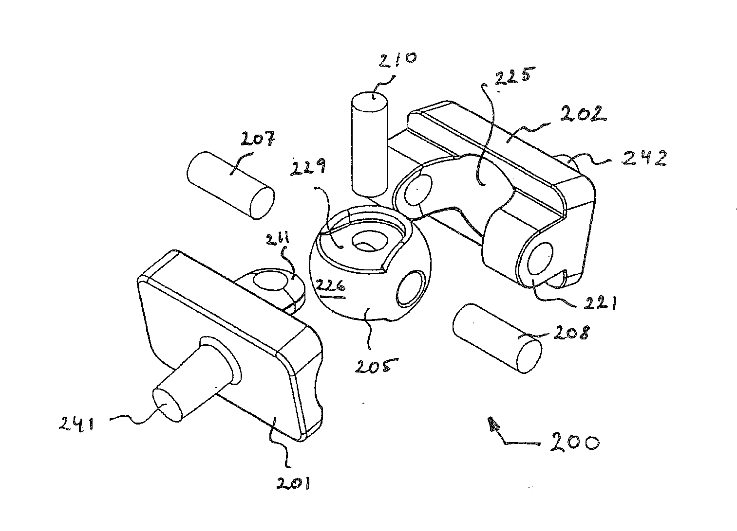
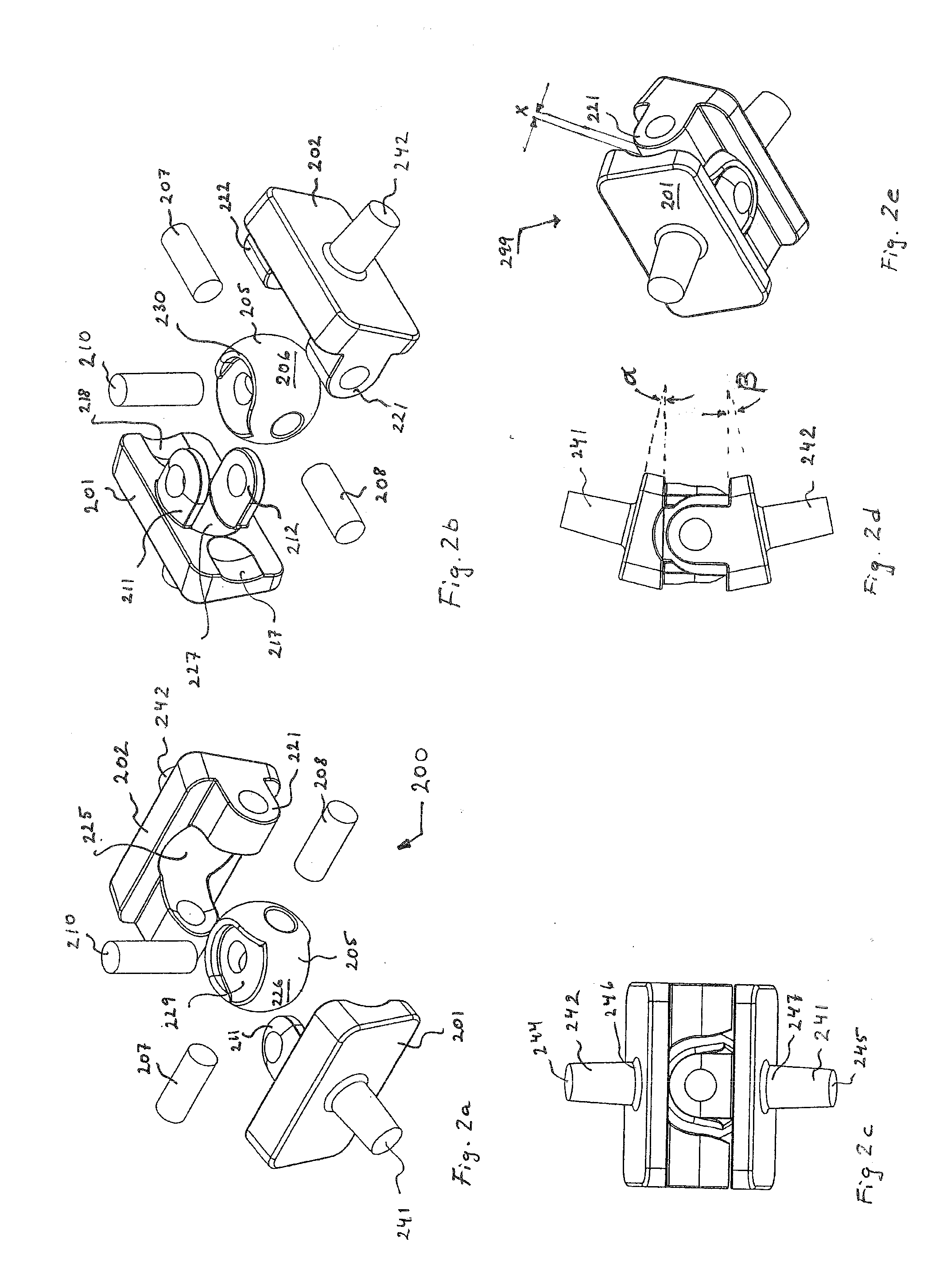
[0053]FIG. 2a illustrates, in a perspective view from distal upper left, an exploded artificial joint 200 according to the present invention. The artificial joint 200 comprises a first base element in the form of a first base plate 201, and a second base element in the form of a second base plate 202, and a ball member 205 designed to be arranged between the first base plate 201 and the second base plate 202. The base plates are preferably rectangular in shape.
[0054]The first base plate 201 is provided with an upper yoke member 211, and a lower yoke member 212 arranged to hold the ball member 205 between them. The upper and lower yoke members are preferably manufactured integral with the base plate. A holding arrangement for the ball member is provided. This may be in the form of bores and pin(s) or just by arranging stub axles at the ball member. In the present embodiment a bore is provided in each yoke member and in the ball member to enable arrangement of a vertical pin passing t...
second embodiment
[0058]an artificial joint according to the present invention is shown in FIGS. 3a to 3e. The artificial joint 300 comprises a first base element 301 with upper 311 and lower 312 retaining members, a second base element 302 with left 321 and right 322 retainer members and a cross pin member 305. The cross pin member being manufactured of a high strength material to cope with the proportionally high stressing forces that arise due to the relative small size of the joint and the cross pin member 305. The cross pin member 305 may comprise a cross pin 307, 308, 309, 310 permanently fixed into a spherical body 305, or may comprise a cross pin manufactured integral with a spherical central portion.
[0059]Each of the retaining members 311, 312, 321, 322 have an elongated opening to allow the pins 307, 308, 309, 310 of the cross pin member 305 to be pressed into the retaining members. Retaining members comprises cylindrical surface to make contact to pins to enable a pivoting relationship bet...
PUM
| Property | Measurement | Unit |
|---|---|---|
| Angle | aaaaa | aaaaa |
| Force | aaaaa | aaaaa |
Abstract
Description
Claims
Application Information