Cable management and tie-off apparatus

Active Publication Date: 2010-01-12
PURE SAFETY GRP INC
View PDF22 Cites 3 Cited by
  • Summary
  • Abstract
  • Description
  • Claims
  • Application Information

AI Technical Summary

Benefits of technology

[0011]It is an object of the present invention to provide a cable and / or rope management system. It is another object of the present invention to provide a cable and / or rope management system that effectively and securely ties off suspended cables and / or ropes when draped over hand rails and other barriers.
[0019]The rail rig apparatus of the present invention is designed to fit on multiple size rails and for easy and quick installation. The rail rig apparatus is portable and installs in seconds by simply sliding the lower support onto a lower rail and the upper support onto an upper rail. The adjustable rig fastener member that is attached to the body of the rail rig apparatus at one point is pulled around the lower rail and secured to a second point on the body of the rail rig apparatus. The rail rig apparatus is then ready for use.

Problems solved by technology

When multiple ropes and / or cables are utilized, management of the plurality of ropes and / or cables becomes more difficult.
When this method of tying off is used, there are several disadvantages and problems that can occur.
Most workers are not properly trained (if at all) in tying proper and effective knots.
When the knots are tied, they can be tied too tight making it difficult to release the rope or cables in an effective and timely manner.
On the other hand, if the knots are not tied secure enough, there is the risk of premature release of the cable and / or rope.
Additionally, tying the rope or cable often requires the use of two hands, which can be cumbersome at times and inconvenient and counter-productive.
Crane wells, open bays, and scaffolding platforms where there are hand rails in place for safety purposes are other examples where ropes and / or cables can be problematic.
In some cases, lifting these buckets and equipment can potentially span several building floors.
During the lifting operation, the potential for the rope to release from the workers hands due to fatigue or accidental release can be a safety hazard for workers and passersby below.

Method used


Image

  • Cable management and tie-off apparatus
  • Cable management and tie-off apparatus
  • Cable management and tie-off apparatus

Examples


Embodiment Construction

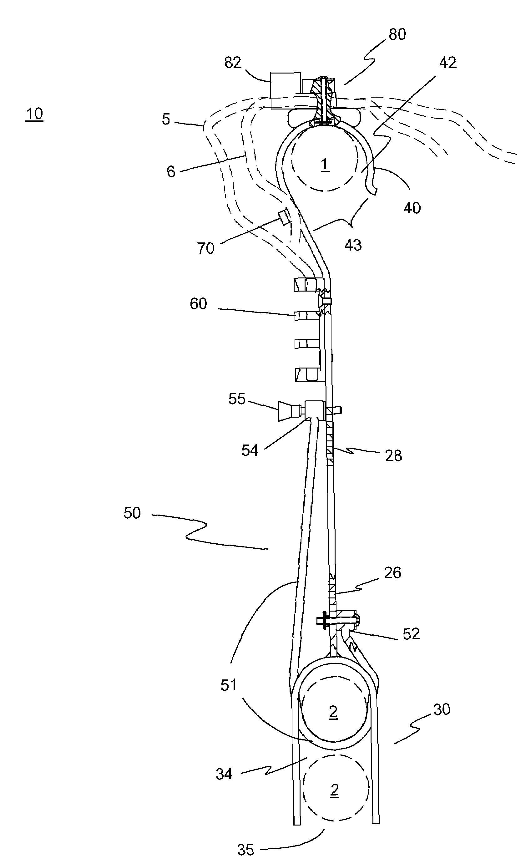
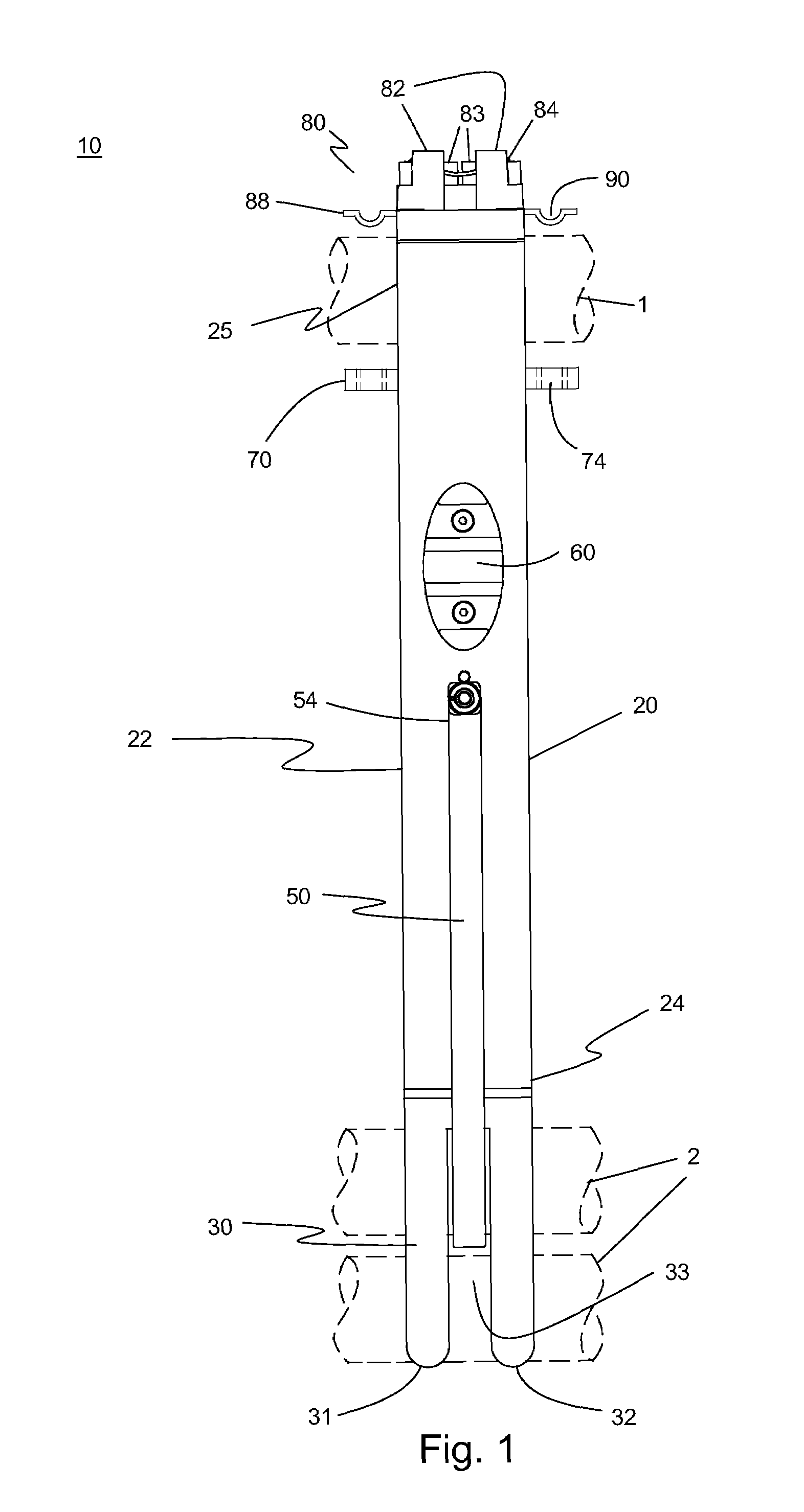
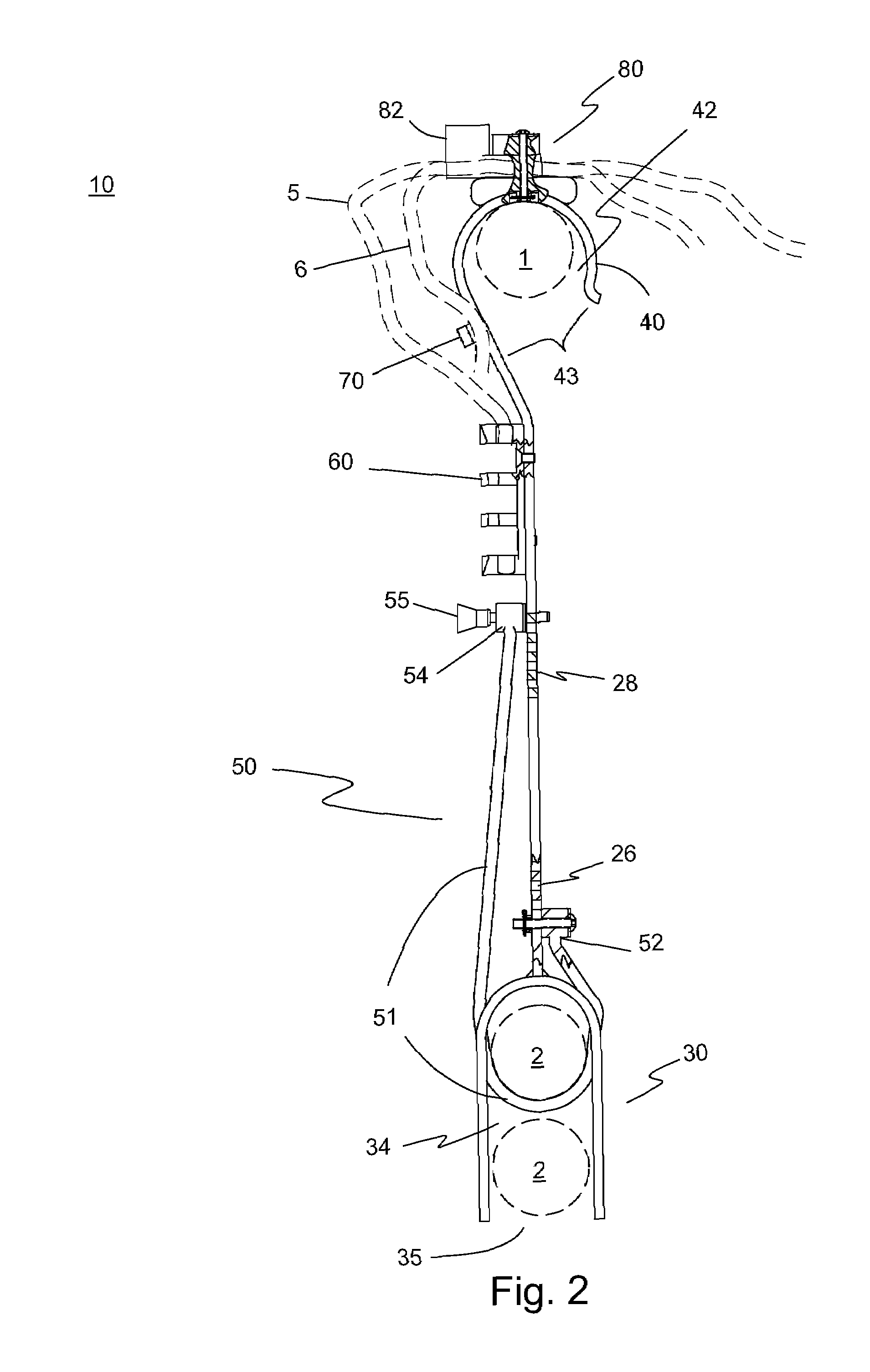
[0024]The preferred embodiment of the present invention is illustrated in FIGS. 1-4. FIG. 1 illustrates a rail rig apparatus 10 of the present invention. Rail rig apparatus 10 includes a body 20, a lower support 30, an upper support 40 (more clearly shown in FIG. 2), an upper guide mechanism 80, a rig fastener member 50, and an optional securing cleat 60. Body 20 may be solid or tubular and includes a middle portion 22, a lower body end 24 and an upper body end 25. Lower support 30 is formed at a lower body end 24 of body 20 and preferably includes a forked shaped structure having a first set of lower support extensions 31 and an optional second set of lower support extensions 32. When optional second set of lower support extensions 32 are included, a space 33 between the first set of lower support extensions 31 and the optional second set of lower support extensions 32 is provided to preferably accommodate rig fastener member 50 therethrough. Rig fastener member 50 is removably con...


PUM


Abstract

A rail rig apparatus includes a body having a middle portion, lower end and an upper end, a lower support having a lower support recess with a lower recess opening, the lower support connected to the lower end of the body, a rig fastener member having a first fastener body end connected to one side of the body, a second fastener body end connected to an opposite side of the body, and a fastener member body extending from the first fastener body end around the lower support recess to the second fastener end, an upper support having an upper support recess with an upper recess opening connected to the upper end of the body, and an upper rope guide mechanism connected to the upper support wherein the upper rope guide mechanism has a pair of opposed jaws defining a space therebetween to receive and secure a rope.

Description

BACKGROUND OF THE INVENTION[0001]1. Field of the Invention[0002]The present invention relates generally to cables and ropes. The present invention relates to devices for managing cables and ropes.[0003]2. Description of the Prior Art[0004]Ropes, cables, cords and the like have been used for many years in a wide variety of applications. When used, there is undoubtedly a need at some point to secure the robes, cables and the like. Typically, ropes are tied into a knot.[0005]Clamping mechanisms can also be used for cables, ropes and the like. When multiple ropes and / or cables are utilized, management of the plurality of ropes and / or cables becomes more difficult.[0006]For example, in the nuclear power industry, long handled poles are typically used to deliver tooling, lighting, cameras, etc., in and around the reactor cavity and spent fuel pools. In this particular application, cables are normally used to operate the tooling from a remote location. Frequently, these long handled poles ...

Claims


Application Information

Patent Timeline
IPC IPC(8): F16L3/00
CPCH02G11/00
Inventor MOREAU, DARRELL A.MOREAU, ANDRE W.
Owner PURE SAFETY GRP INC
Why Eureka
Try Eureka