Electrical branch junction connector

Inactive Publication Date: 2006-02-16
WAGO VERW GMBH
View PDF8 Cites 1 Cited by
  • Summary
  • Abstract
  • Description
  • Claims
  • Application Information

AI Technical Summary

Benefits of technology

[0006] The object of the present invention consists of developing a branch junction connector of the generic kind that may be used universally for all kinds of contact tap elements and that, at the same time, can be quickly and easily installed by the electrical installer.

Problems solved by technology

However, the forces that need to be applied for this are as a rule very large and cannot be produced by an electrical installer without auxiliary tools.
However, a drawback is that a screwing technology of this kind may be used only for needle-shaped piercing contacts or for other needle-shaped contacts of the piercing type.

Method used


Image

  • Electrical branch junction connector
  • Electrical branch junction connector

Examples


Embodiment Construction

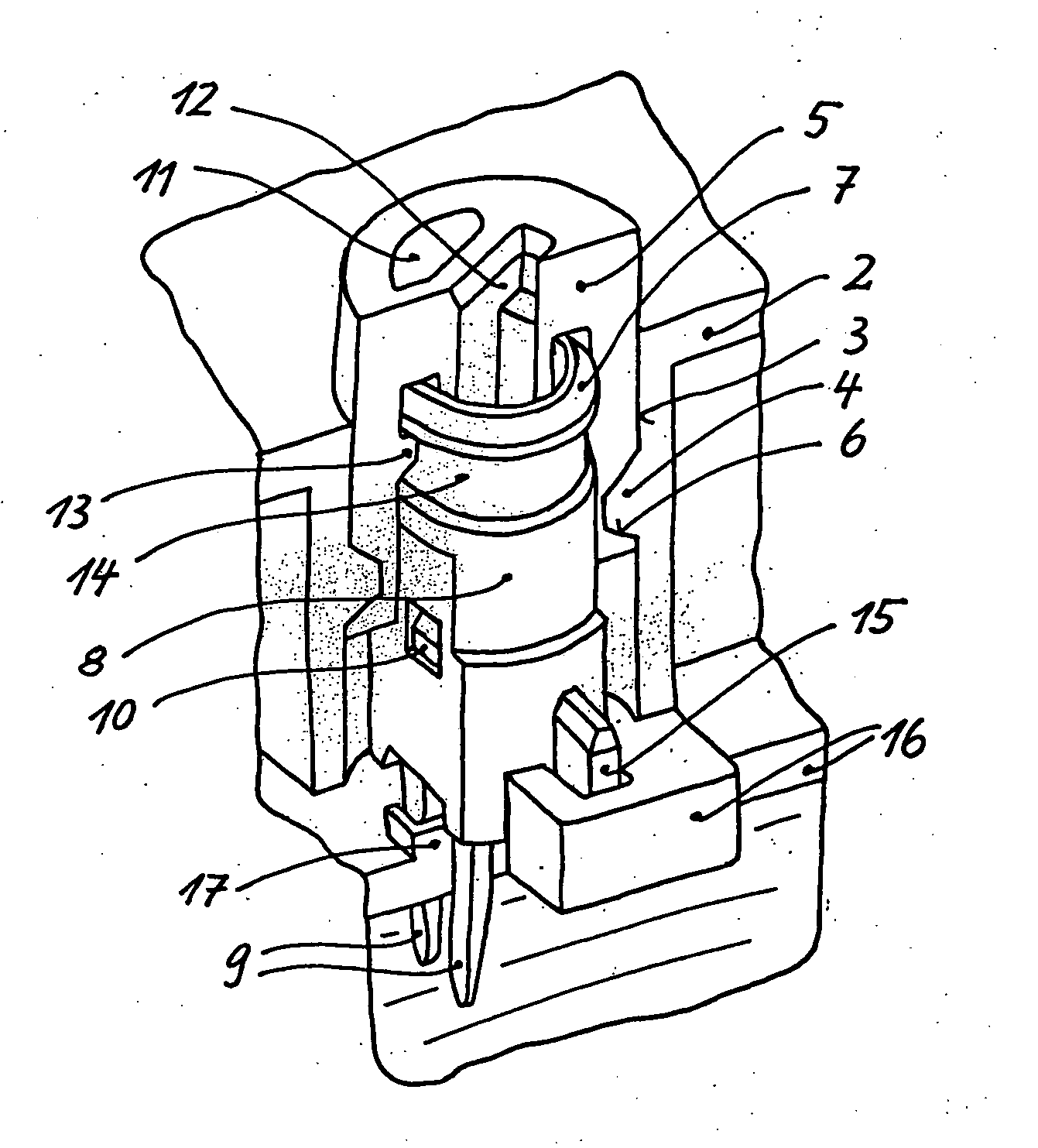
[0024]FIG. 1 shows, in perspective depiction, the region of a contact tap element, of which there are several for a branch junction connector of the invention. Depicted is the insulation housing 2 with the housing cylinder bore 3, which has a projecting, one-turn thread 4, preferably consisting of two opposite-lying parts, each with a circumferential extension of 120° (not shown individually).

[0025] In the housing cylinder bore, in accordance with the teaching of the invention, a cylinder cap 5 is inserted and screwed onto the thread 4 of the cylinder bore. For this purpose, the thread on the side of the cylinder cap is formed as a depression as a thread groove 6 on the bottom edge of the cylinder wall of the cylinder cap.

[0026] The cylinder cap overlaps the rotating thrust bearing 7 of the contact tap element, which, in the case of the embodiment example depicted, consists of the plastic body 8 with the rotating thrust bearing 7 and a bottom-side, fork-shaped insulation displacem...


PUM


Abstract

The invention relates to a branch junction connector for self-stripping electrical contact of cable wires of electrical lines. It is proposed that, for this purpose, an advancing rotating cylinder be used, which is joined, via a rotating thrust bearing, with a contact tap element that is guided in a linear manner in an insulation housing in such a manner as to be rotationally rigid and to withstand pulling and pushing.

Description

TECHNICAL FIELD [0001] The invention relates to a branch junction connector for producing a self-stripping electrical contacting of cable wires of electrical lines that have insulation and / or sheathing and the respective tap zones of which are held in a fixed position parallel to one another in an insulation housing, whereby the contact tap per cable occurs in each case by means of a contact tap element in the insulation housing that can move in a guided manner perpendicular to the cable and that cuts through the insulation and / or sheathing and contacts the cable wires. BACKGROUND DISCUSSION [0002] Such branch junction connectors are known for making electrical contact of power supply cables (phase leads, neutral leads, earth leads) as well as for making branch contact of data cables, control cables, etc. The cables can exist as parallel single cables or they can be in the form of a flat ribbon cable having a defined wire-to-wire spacing. It is always the case that they are held in ...

Claims


Application Information

Patent Timeline
IPC IPC(8): H01R4/24H01R12/08
CPCH01R4/2433H01R12/675H01R12/616
Inventor GERBERDING, WOLFGANG
Owner WAGO VERW GMBH
Why Eureka
Try Eureka