Twist-base mount

Inactive Publication Date: 2017-10-05
STENDER TIMOTHY P
View PDF26 Cites 2 Cited by
  • Summary
  • Abstract
  • Description
  • Claims
  • Application Information

AI Technical Summary

Benefits of technology

[0005]The Twist-Base Mount solves the preceding dilemma by its unique structure, which couples a single-screw, substrate-penetrating element with a flexible, concave base element that, once installed, acts as a spring, exerting a downward force upon the substrate around its circumference. Because the base element is rigidly attached to the substrate-penetrating element, a force applied to the mount parallel to the plane of the substrate is offset by the pressure of the perimeter of the base element against the substrate, resulting in additional strength. Yet the mount's single-screw, self-boring, subs

Problems solved by technology

For example, a strong mount would be expected to cost more, due to its complexity or materia

Method used


Image

  • Twist-base mount
  • Twist-base mount
  • Twist-base mount

Examples


Example

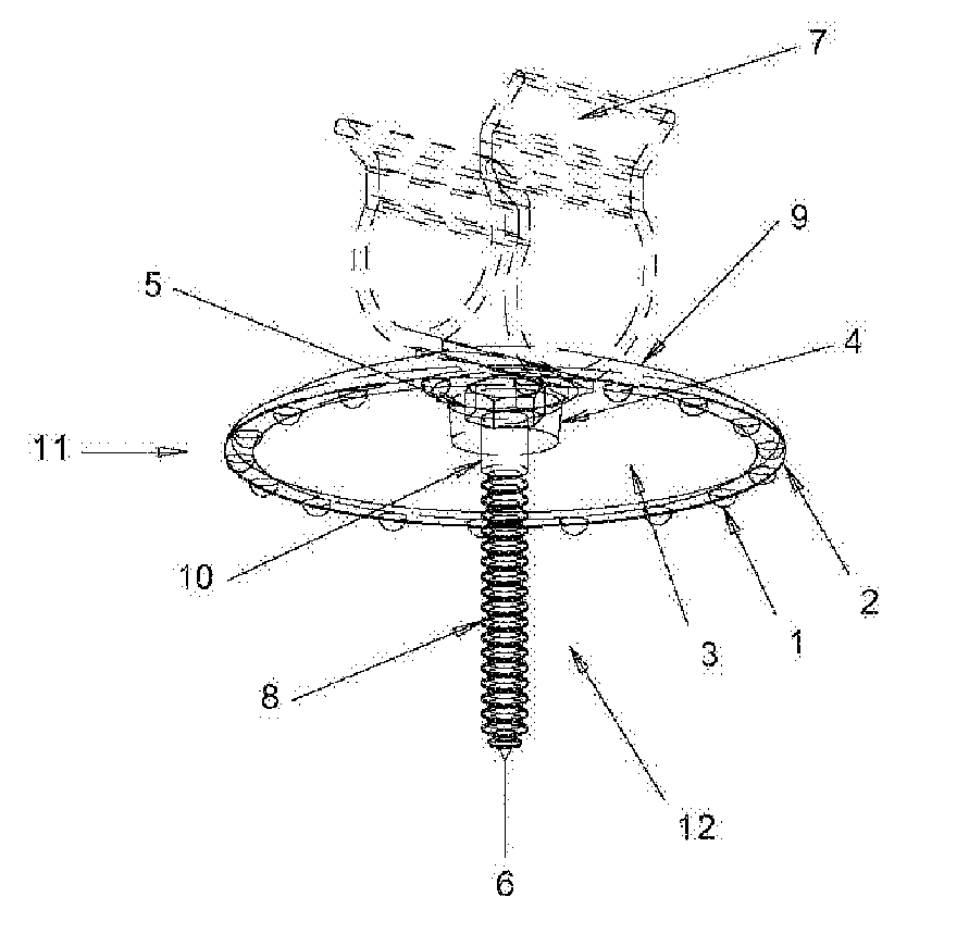
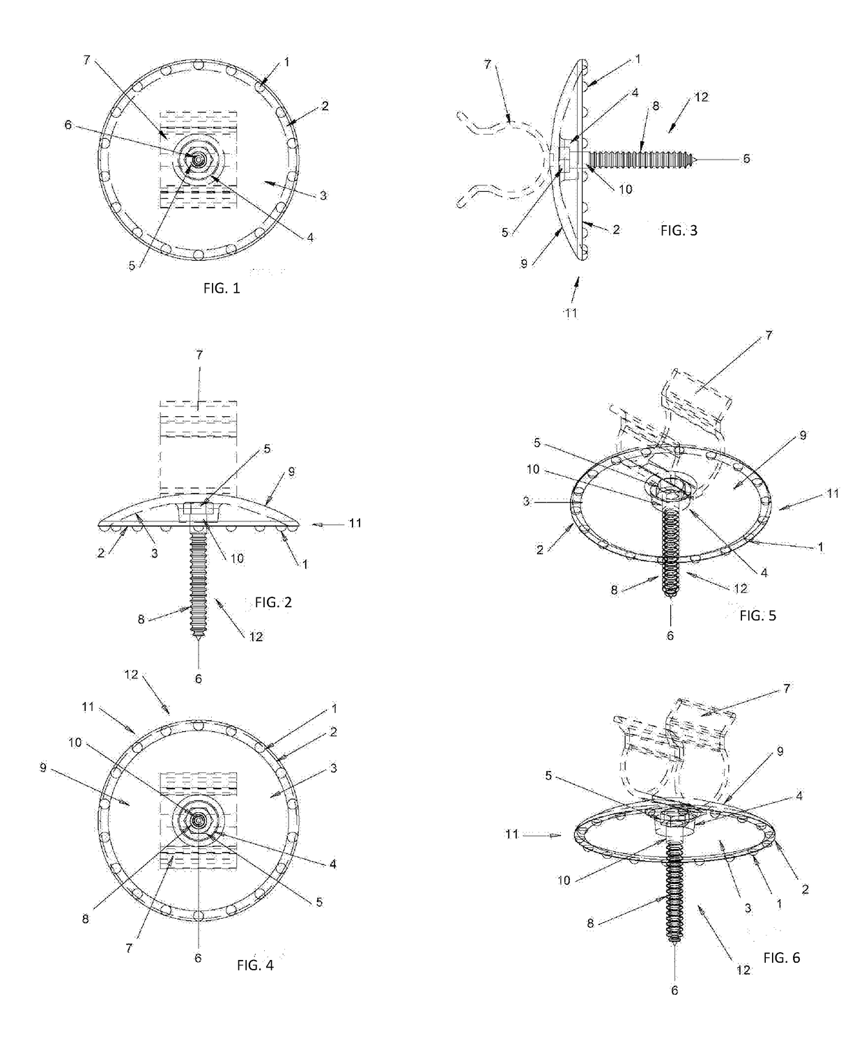
[0016]Referring to FIGS. 1-6, a stable, rotatably-adjustable, self-boring mount for fixtures (the “Twist-Base Mount” or “Mount”), comprises a hollow, deformable, dome-shaped base element 11 made of a thermoplastic material. The dome shape can be a section of a sphere or an ellipsoid cut by a plane in which the ratio of the width of the base to the height of the base can be between 4 inches and 8 inches. The diameter of the base can be from 1.5 inches to 2.5 inches. A self-boring, screw element 12 is attached to the underside of the base element. Base element 11 comprises a convex, fixture-supporting topside portion 9, a concave, substrate-facing, underside portion 3 opposite the topside portion, a generally cylindrical or frustoconical hub 4 extending perpendicularly away from the center of said underside portion 3, and a substrate-engaging portion defined by a circumferential edge 2. A plurality of protuberances 1 (each, a “detent” or “nub”) are defined on the circumferential edge ...


PUM


Abstract

The Twist-Base Mount couples a single-screw, substrate-penetrating element with an elastically-deformable, concave base element that, once installed, acts as a spring, exerting a downward force upon the substrate around its circumference. Because the base element is rigidly attached to the substrate-penetrating element, a force applied to the Mount parallel to the plane of the substrate is offset by the pressure of the perimeter of the base element against the substrate, resulting in additional strength. The Mount's single-screw, self-boring element allows quick and easy installation. The spring-like base-element permits 360-degree rotation of the Mount while maintaining uniform pressure against the substrate, thereby preserving strength regardless of rotational positioning. The mount remains economical in relation to mounts of similar strength and rotational adjustability due to its insert-molded construction.

Description

CROSS-REFERENCE TO RELATED APPLICATIONS[0001]Not Applicable.BACKGROUND OF THE DISCLOSURE[0002]This invention pertains to the field of mounts and mounting systems, and more particularly to a single-screw, rotatable mounting system for affixing a fixture to a substrate.[0003]The related art includes mounting systems that comprise a planar base element designed to rest against a substrate and a substrate-penetrating element that extends orthogonally downward from the base element for affixing the mount to the substrate.[0004]Mounting systems vary in strength (the amount of weight that can be supported when affixed to given substrate), speed of installation (the amount of time required to affix the mount to a substrate), rotational adjustability (the degree to which the mount can pivot after installation while maintaining strength), and economy (the degree to which the mount is not costly). While all four attributes are desirable, they are, in general, mutually exclusive or offsetting. ...

Claims


Application Information

Patent Timeline
IPC IPC(8): F16M13/02F16L3/02F16M11/06
CPCF16M13/02F16L3/02F16M11/06F16L3/01F16L3/13F16B5/0685
Inventor STENDER, TIMOTHY P.
Owner STENDER TIMOTHY P
Why Eureka
Try Eureka