Optical connection structure of optical backplane to circuit substrate
a technology of optical backplane and circuit substrate, which is applied in the field of optical backplane, can solve the problems of limited transmission speed of electric substrate used in equipment, drawback to the increase of equipment capacity, and difficulty in attaching connectors, so as to achieve the effect of increasing the density of the circuit substrate to the optical backplan
- Summary
- Abstract
- Description
- Claims
- Application Information
AI Technical Summary
Benefits of technology
Problems solved by technology
Method used
Image
Examples
first embodiment
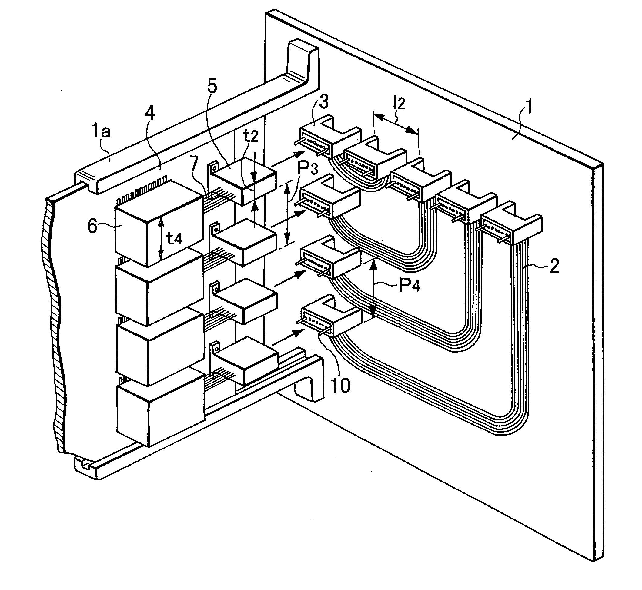
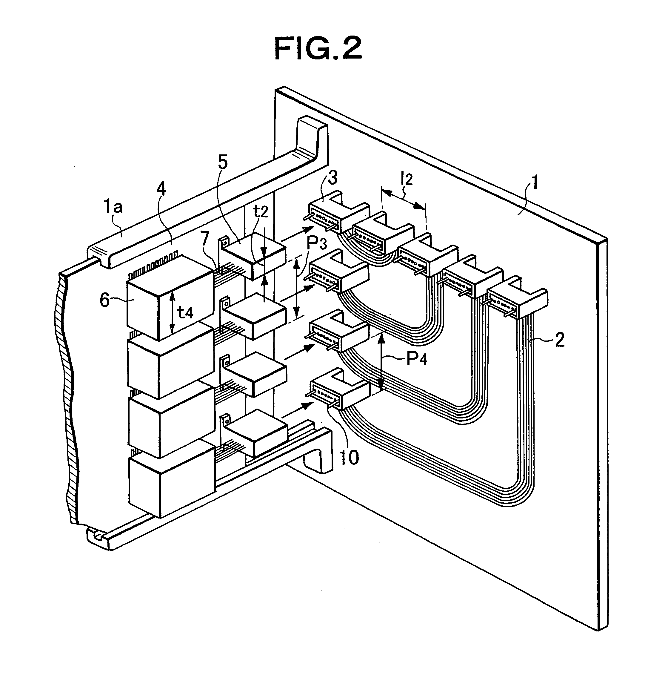
[0042]FIG. 2 is a perspective view showing a connecting portion between a circuit substrate and the optical backplane of a first embodiment according to the present invention in information processing equipment. FIG. 5 is a perspective view showing an overall arrangement of the information processing equipment.
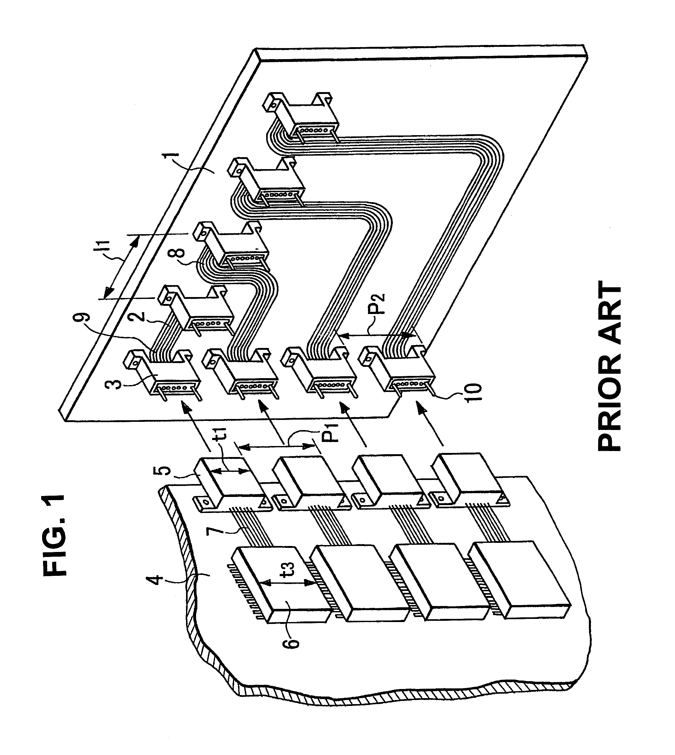
[0043]As shown in FIG. 5, in the information processing equipment, a plurality of circuit substrates 4 are accommodated in a cabinet 31, and the plurality of circuit substrates 4 are disposed to an optical backplane 1 at about right angles. Optical connectors 5 and photoelectric conversion modules 6 on the circuit substrates side are disposed on the circuit substrates 4, and optical connectors 3 on the optical backplane side are disposed to the optical backplane 1. The optical connectors 3 are optically connected to the optical connectors 5. There are, for example, a router, a server, and the like as the information processing equipment according to the first embodiment.
[0044]...
second embodiment
[0058]FIGS. 7A to 7C are views showing a connecting portion of a circuit substrate and optical backplane of a second embodiment of the present invention in the information processing equipment. FIG. 7A is an exploded sectional view of an arrangement of the third embodiment when viewed from the upper surface of a board, FIG. 7B is a view when viewed from the front surface of an optical backplane, and FIG. 7C is a sectional view of a state that the board is inserted into the optical backplane when viewed from the upper surface of the board.
[0059]An overall arrangement of the information processing equipment of the third embodiment is different from the first embodiment in that no photoelectric conversion module is mounted on the circuit substrate, an electric connector is disposed on the circuit substrate, an photoelectric conversion module is disposed in an electric connector on the optical backplane, and the photoelectric conversion module is directly connected to an optical connect...
third embodiment
[0084]FIG. 16 is a perspective view showing a connecting portion between a circuit substrate and the optical backplane in a third embodiment of the present invention in information processing equipment. In FIG. 16, the same components as those of FIGS. 2 and 15 are denoted by the same reference numeral, and the explanation thereof is omitted.
[0085]In the third embodiment, optical connectors 3-1 are disposed in about parallel to the main surface of a board 4 and optical connectors 3-2 are disposed at about a right angle to the main surface of the board 4. The disposing direction of the optical fibers of the optical connectors 3-1 is in about parallel to the main surface of a board 4 in the same way as the optical connectors 3 of FIG. 1. The disposing direction of the optical fibers of the optical connectors 3-2 is in nonparallel (here, at about a right angle) to the main surface of a board 4 in the same way as the optical connectors 3 of FIG. 2.
[0086]Five boards are attached to the o...
PUM
 Abstract
Description
Claims
Application Information
 - R&D
- Intellectual Property
- Life Sciences
- Materials
- Tech Scout
- Unparalleled Data Quality
- Higher Quality Content
- 60% Fewer Hallucinations
Browse by: Latest US Patents, China's latest patents, Technical Efficacy Thesaurus, Application Domain, Technology Topic, Popular Technical Reports.
© 2025 PatSnap. All rights reserved.Legal|Privacy policy|Modern Slavery Act Transparency Statement|Sitemap|About US| Contact US: help@patsnap.com


