
Recessed while-in-use electrical box

a technology of electrical boxes and recessed sockets, which is applied in the direction of insulated conductors, coupling device connections, cables, etc., can solve the problems of exterior electrical outlets, affecting the safe operation of electrical devices, and electrical hazards, so as to prevent the inadvertent dislodging of plugs and reduce the chance of the interface being exposed to water or contaminants

Inactive Publication Date: 2010-01-12
PASS SEYMOUR
View PDF33 Cites 28 Cited by
  • Summary
  • Abstract
  • Description
  • Claims
  • Application Information

AI Technical Summary

Benefits of technology

"The present invention provides an electrical wiring box assembly that prevents moisture and contaminants from reaching the electrical device installed therein. The assembly includes an inner wall box, an inner wall flange, and a collar wall. The inner wall flange has a plurality of apertures formed therein, and the inner wall box includes a plurality of device mounting bosses. The assembly also includes an intermediate box and an outer wall flange. A cover assembly is also provided. The technical effects of the invention include preventing damage to electrical devices, reducing the risk of fire, and improving the overall safety and reliability of electrical wiring box assemblies."

Problems solved by technology

Obviously, electrical outlets must be protected in some manner because of the substantial possibility of creating an electrical hazard when the energized outlet comes in contact with water or moisture.
Moreover, exterior electrical outlets may also be subjected to various contaminants which may also affect the safe operation of the electrical device.
As such, a small gap is created between the electrical wiring device and the plug itself.
Moreover, the plug may be partially dislodged as a result of contact by persons or objects.
Of course, a partial dislodgement may expose a portion of the energized prongs of the electrical plug causing an electrical safety hazard.

Method used


Image

  • Recessed while-in-use electrical box
  • Recessed while-in-use electrical box
  • Recessed while-in-use electrical box

Examples


Embodiment Construction

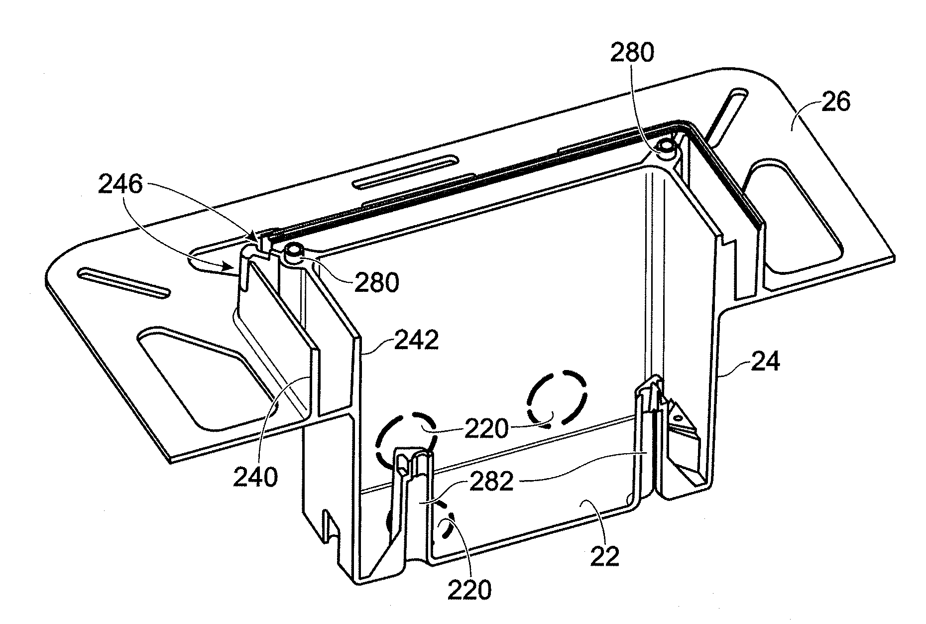
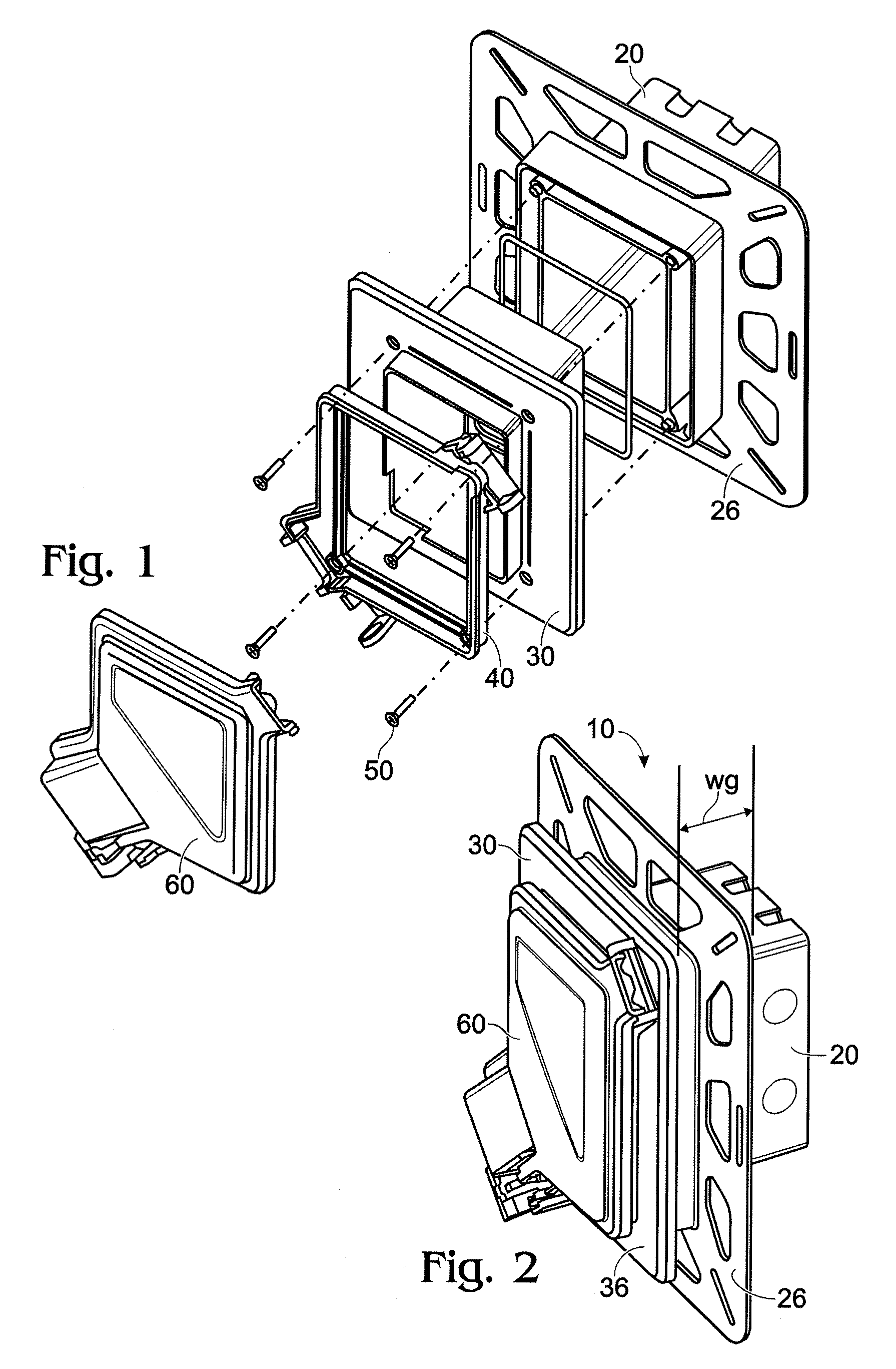
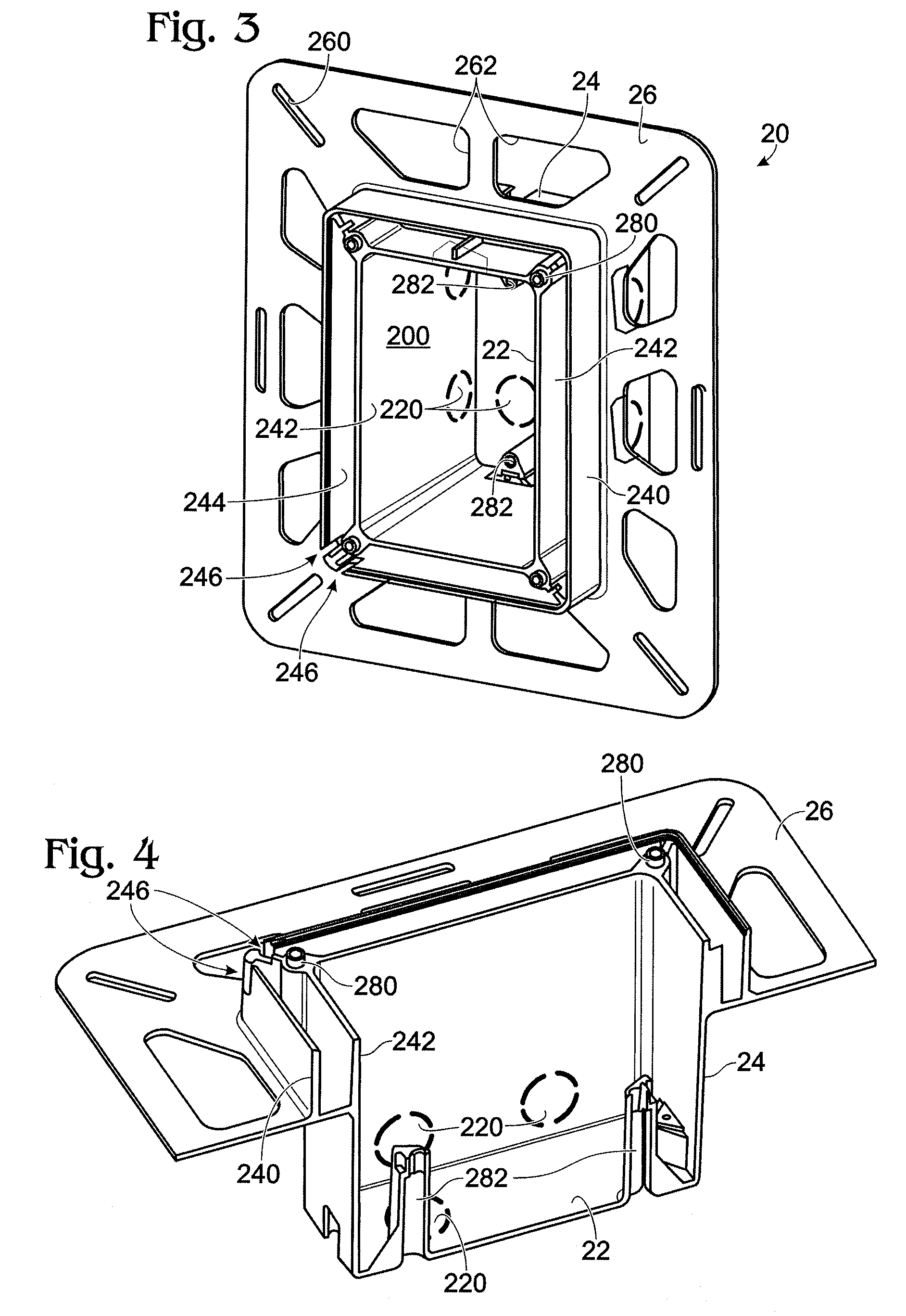
[0026]Reference will now be made in detail to the present exemplary embodiments of the invention, examples of which are illustrated in the accompanying drawings. Wherever possible, the same reference numbers will be used throughout the drawings to refer to the same or like parts. An exemplary embodiment of the recessed while-in-use electrical box assembly of the present invention is shown in FIG. 1, and is designated generally throughout by reference numeral 10.

[0027]As embodied herein, and depicted in FIG. 1, an exploded view of the recessed electrical box assembly 10 in accordance with one embodiment of the present invention is shown. The assembly 10 includes an inner box 20, an intermediate box 30, a cover ring 40, ring mounting screws 50 and a cover member 60. The inner box 20 is configured to be disposed within the wall structure and includes a wall flange 26 that mounts to the wall structure itself. The intermediate box 30 is telescopically disposed within the inner box 20 and...


PUM


Abstract

The present invention is directed to an electrical wiring box assembly that includes an inner wall box including a peripheral inner wall bounded and enclosed by a rear wall and open at a front end of the inner wall box to form an inner volume. The inner wall box also includes an inner wall flange extending in a substantially perpendicular direction from an exterior surface of the peripheral inner wall at predetermined distance from the front inner wall box end. The inner wall flange includes a plurality of apertures formed therein. The inner wall box further includes a plurality of device mounting bosses extending in a substantially perpendicular direction from an interior surface of the rear wall. An intermediate box includes a peripheral intermediate wall portion configured to fit within the inner volume. The peripheral intermediate wall is bounded by a rear ledge extending inwardly and perpendicularly from a back end of the peripheral intermediate wall to form an intermediate volume in communication with the inner volume at the back end and open at a front intermediate wall box end The intermediate box further includes an outer wall flange extending in a substantially perpendicular direction from an exterior surface of the peripheral intermediate wall at predetermined distance from the front end of the peripheral intermediate wall. A rear wall portion of the outer wall flange is configured to abut the front inner wall box end such that the rear edge is substantially aligned with the plurality of device mounting bosses. A cover assembly is removably coupled to the intermediate box, the cover assembly providing access to the intermediate volume in an open position and substantially sealing the intermediate volume and the inner volume in a closed position.

Description

BACKGROUND OF THE INVENTION[0001]1. Field of the Invention[0002]The present invention relates generally to electrical wiring boxes, and particularly to electrical wiring box assemblies.[0003]2. Technical Background[0004]In many cases it is desirable to provide electrical outlets on the exterior wall of both residential and commercial structures. Homeowners, maintenance and repair personnel and contractors require such electrical outlets to provide electrical power to electrically operated appliances, tools and other such devices. Obviously, electrical outlets must be protected in some manner because of the substantial possibility of creating an electrical hazard when the energized outlet comes in contact with water or moisture. An exterior outlet may come in contact with water by any number of ways, such as rainfall, melting snow, or by way of human activity in close proximity to the outlet. Activities such as watering plants and shrubbery, or children playing with the water hose ar...

Claims


Application Information

Patent Timeline
Patent Type & Authority Patents(United States)
IPC IPC(8): H01H9/02
CPCH02G3/123H02G3/14
Inventor BHOSALE, VIKRAMSINH P.
Owner PASS SEYMOUR
Learn More