Test carriers for storage devices

a storage device and carrier technology, applied in the direction of magnetic recording, record carrier contruction details, magnetic disk recording, etc., can solve the problems of sff storage device time delay, bed clamping and damping features are limited, and existing testing beds do not facilitate quick connection and disconnection

Inactive Publication Date: 2010-01-12
INNOVATIVE POLYMERS PTE
View PDF9 Cites 87 Cited by
  • Summary
  • Abstract
  • Description
  • Claims
  • Application Information

AI Technical Summary

Benefits of technology

[0014]a tester interfacewhere, when the slider tray is in a first position, the storage device can be received within the at least one aperture of the slider tray and, when the slider tray is in a second position, an interface of the storage device mates with the storage device connector, appropriate circuitry contained in the carrier base connecting the tester interface and the storage device connector thereafter allowing the storage device to be tested via the tester interface.

Problems solved by technology

In the manufacture of storage devices, and in particular SFF storage devices, there are a number of problems that the manufacturer is presented with, such as:testing beds are typically designed for 3.5″ storage devices.
Testing beds of alternate sizes need to be custom made which delays the time to market of SFF storage devices.existing testing beds do not facilitate the quick connection and disconnection of the storage device to be tested.existing testing beds have limited clamping and damping features, if any.
This affects the performance of the storage device under test.

Method used


Image

  • Test carriers for storage devices
  • Test carriers for storage devices
  • Test carriers for storage devices

Examples


first embodiment

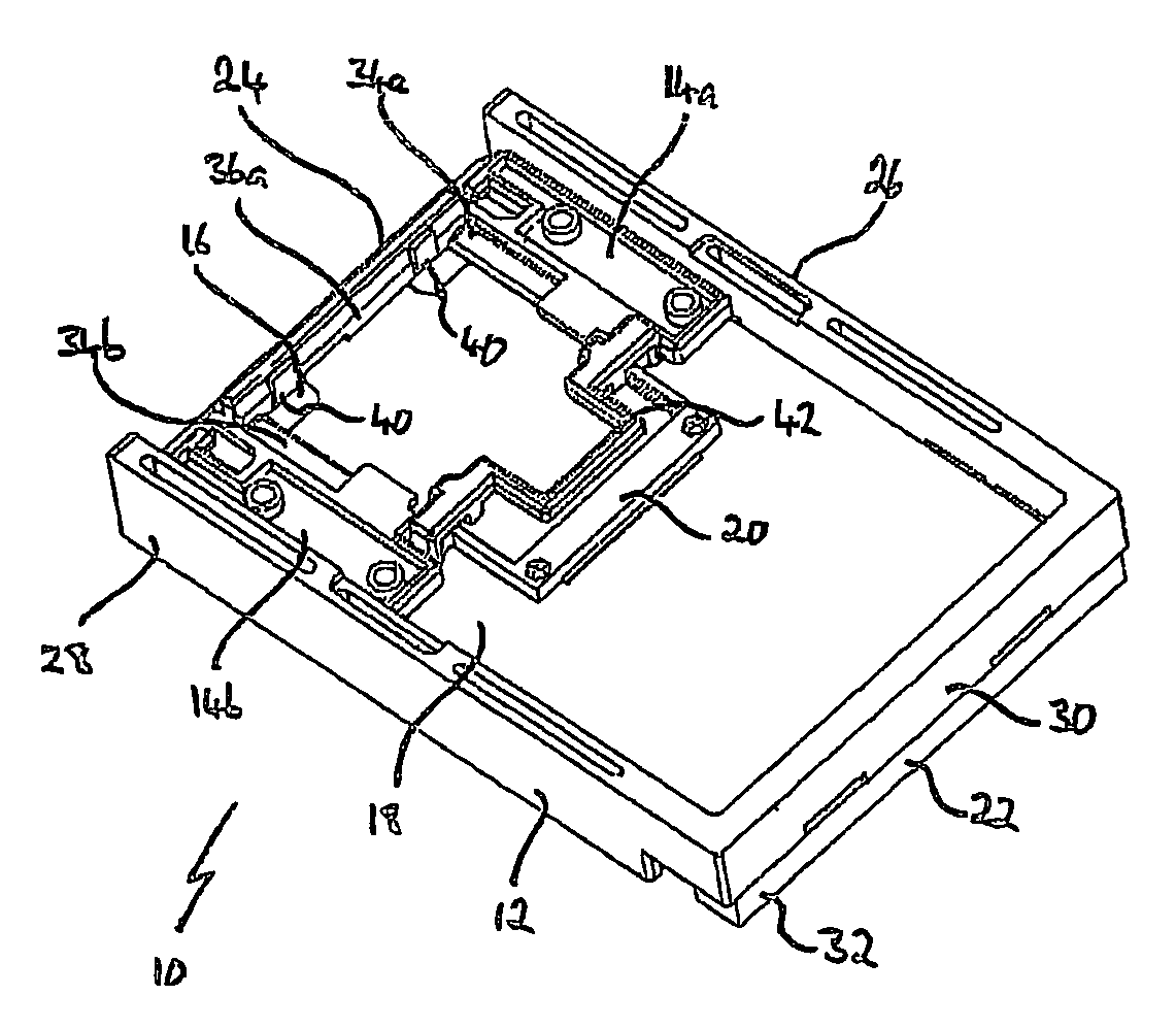
[0035]In accordance with the invention there is a single-unit test carrier 10 as shown in FIG. 1. The test carrier 10 comprises a carrier base 12, slider guides 14a, 14b, a slider tray 16, an interface PCBA 18, a storage device connector 20 and a tester / host interface PCBA 22.

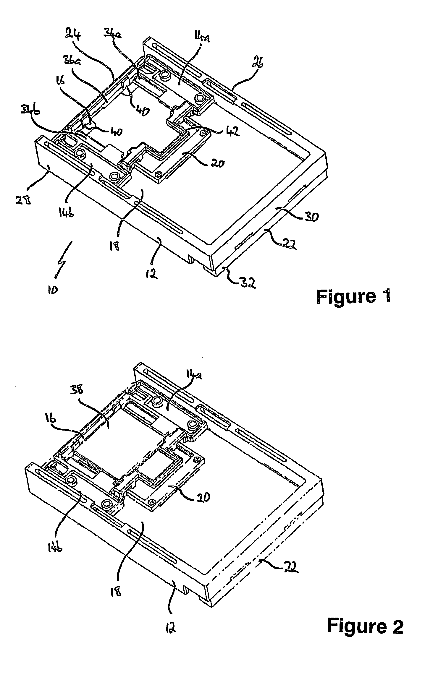
[0036]Each slider guide 14 is mounted to the carrier base 12 at a first end 24. Slider guide 14a is mounted to the carrier base 12 at the first end 24 adjacent side wall 26. Slider guide 14b is mounted to the carrier base 12 at the first end 24 adjacent side wall 28. The slider tray 16 is positioned between the slider guides 14a, 14b and connected thereto in a manner that permits the slider tray 16 to move in the direction from first end 24 towards a second end 30. This is illustrated in FIGS. 2 and 3.

[0037]The interface PCBA 18 is mounted centrally on the carrier base 12. The interface PCBA 18 abuts slider guides 14a, 14b and extends between side wall 26 and side wall 28. Storage device connector 20 is mounted...
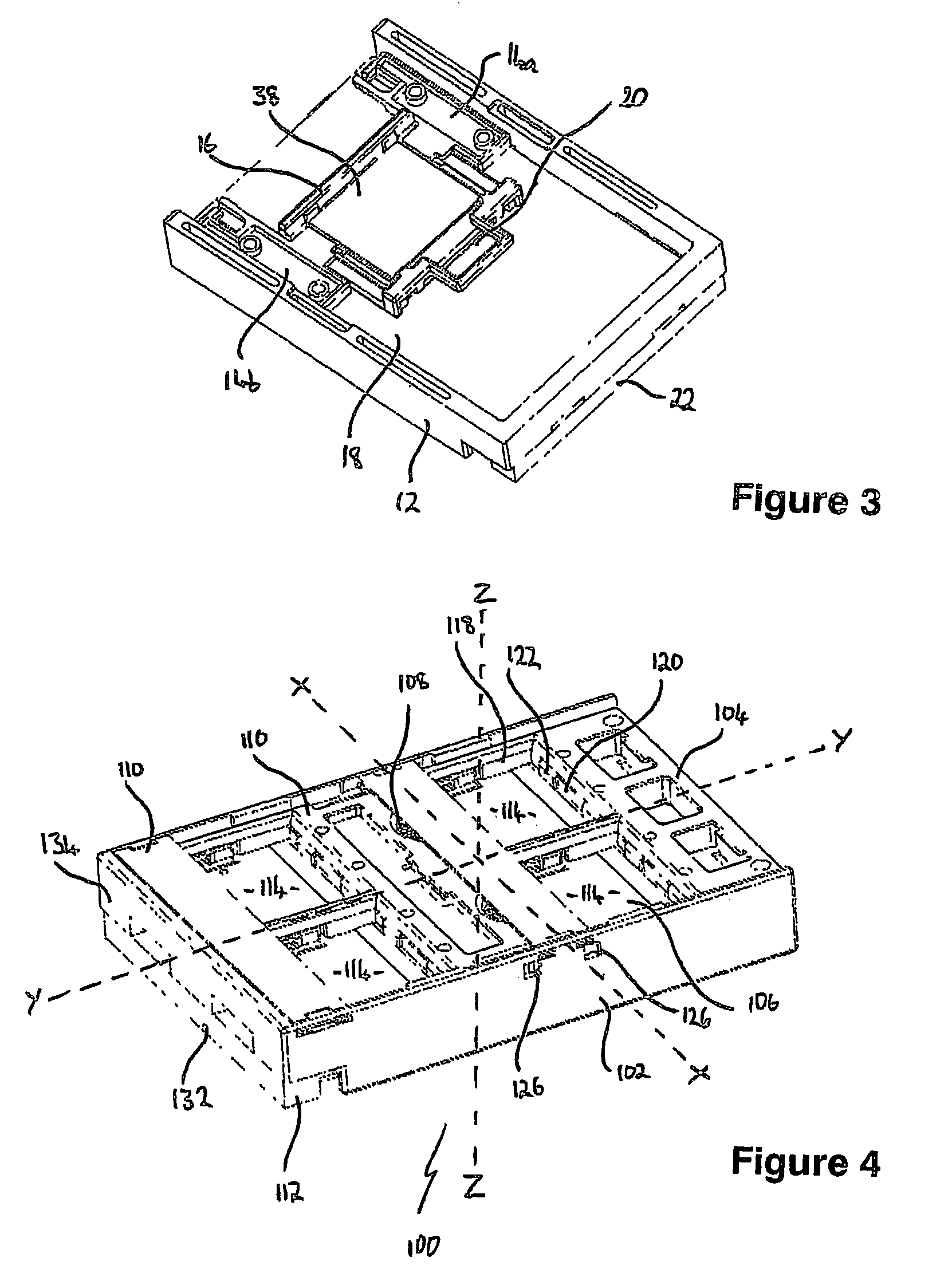
second embodiment

[0064]It should be appreciated by the person skilled in the art that the invention is not limited to the embodiments described above. In particular, the following modifications may be made without departing from the scope of the invention:[0065]1. The connector portions 32, 134 may be omitted in its place the circuitry required to effectively test the storage device may be built into the tester / host interface PCBA 22, 112.[0066]2. The test carrier 10, 100 may be adapted to be used in HDD tester units having a test bed size greater than or less than the 3.5″ HDD tester unit mentioned above.[0067]3. The clip mechanism 124 may be replaced with other mechanisms by which the slider tray 104 may be securely retained in both the load and unload positions.[0068]4. The slider tray 104 of the second embodiment may be modified to adapt to any number of SFF storage devices that can be fitted within the carrier base 102.


PUM


Abstract

A test carrier 10 for storage devices 38 comprising a carrier base 12; a slider tray 16 slidably mounted to the carrier base 12, the slider tray 16 having at least one aperture for receiving a storage device 38 therein; at least one storage device connector 20 connected to the carrier base 12; and a tester interface 22, where, when the slider tray 16 is in a first position, the storage device 38 can be received within the at least one aperture of the slider tray 16 and, when the slider tray 16 is in a second position, an interface of the storage device 38 mates with the storage device connector 20; appropriate circuitry contained in the carrier base 12 connecting the tester interface 22 and the storage device connector 20 thereafter allowing the storage device 38 to be tested via the tester interface 22.

Description

FIELD OF THE INVENTION[0001]The present invention relates to a test carrier for storage devices. The invention is particularly suited to testing one inch and sub-one inch storage devices, hereafter referred to as small-form-factor (“SFF”) storage devices, in a 3.5″ hard disk drive tester.BACKGROUND ART[0002]The following discussion of the background invention is intended to facilitate an understanding of the present invention. However, it should be appreciated that the discussion is not an acknowledgment or admission that any of the material referred to was published, known or part of the common general knowledge in any jurisdiction as at the priority date of the application.[0003]In all manufacturing processes the product manufactured is subject to certain quality control requirements. In respect of products, this generally involves testing using one or more testing devices.[0004]In the manufacture of storage devices, and in particular SFF storage devices, there are a number of pro...

Claims


Application Information

Patent Timeline
Patent Type & Authority Patents(United States)
IPC IPC(8): H05K7/20
CPCG11B25/043G11B33/12
Inventor NG, BEE KEONG
Owner INNOVATIVE POLYMERS PTE
Why Eureka
Try Eureka