
Slide module for a slide type electronic device

a technology of slide and electronic device, applied in the field of slide module, can solve the problems of easy damage to the electronic device, keypad can be pressed, electronic device, etc., and achieve the effect of reducing the friction between the roll edge and the guide recess

Inactive Publication Date: 2010-01-12
CHENG UEI PRECISION IND CO LTD
View PDF1 Cites 17 Cited by
  • Summary
  • Abstract
  • Description
  • Claims
  • Application Information

AI Technical Summary

Benefits of technology

[0011]As described above, because of the slick guide recesses of the slide rails and the corresponding roll edges of the slide base, the friction of the motion between the roll edges and the guide recesses is reduced. Then the slide base slides along the slide rails smoothly.

Problems solved by technology

A bar type electronic device, since its keypad is exposed, can easily be damaged or the keypad can be pressed by mistake.
However, it still remains the same problem, which the bar type electronic device has, that the housing size of the electronic device itself is too long to carry conveniently.
Further, the flip type electronic device fails to satisfy the demand for a larger display screen in order to review the data from Internet access.
However, the hinges that connect an upper folder and a lower folder can easily be damaged because these folders have to be opened and closed repeatedly.
However, the conventional slide module as described above is not exquisite enough.
In another word, the sliding operation between the slide member and the support plate is not smooth enough.
That may shorten the using life of the slide module.

Method used


Image

  • Slide module for a slide type electronic device
  • Slide module for a slide type electronic device
  • Slide module for a slide type electronic device

Examples


Embodiment Construction

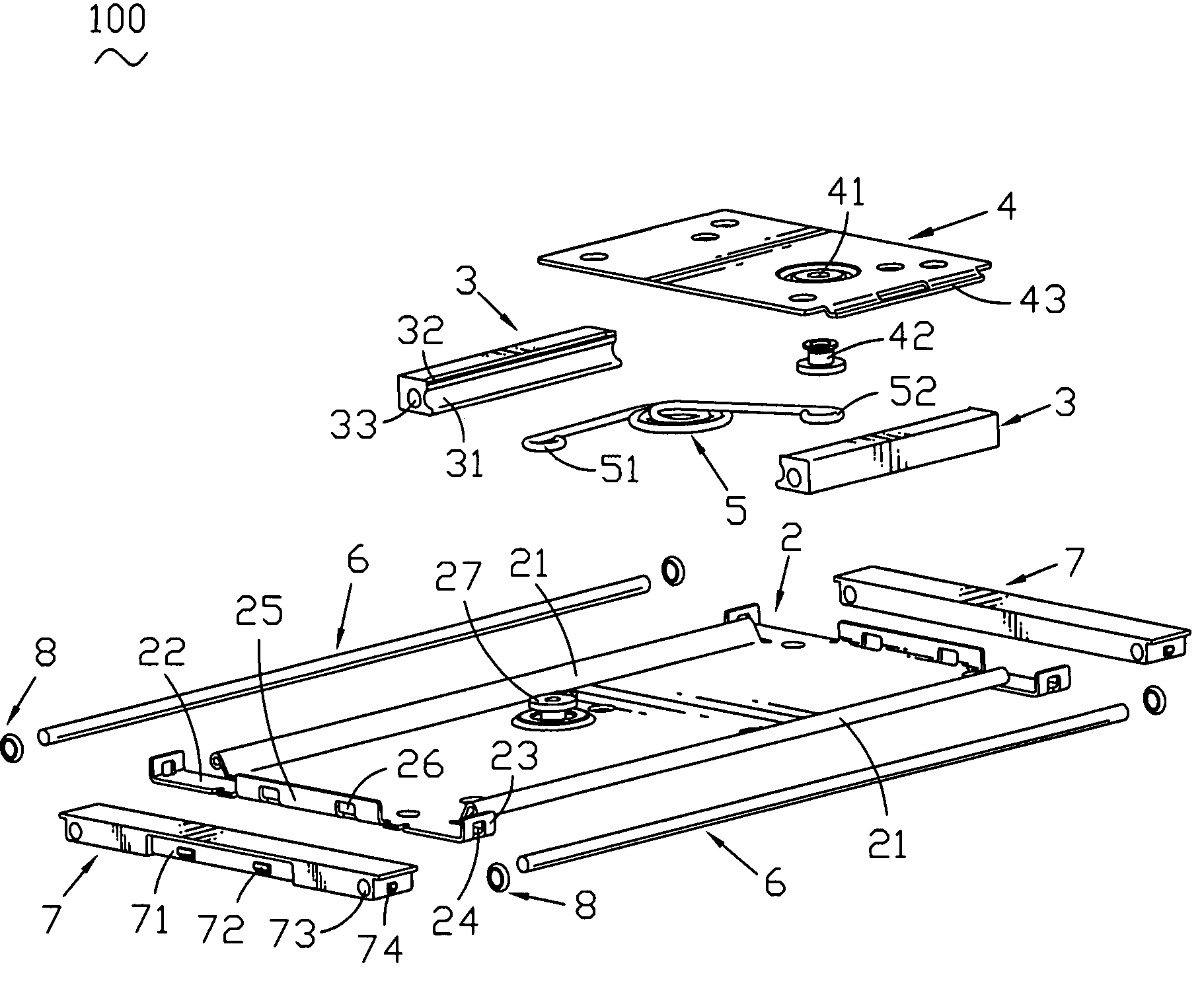
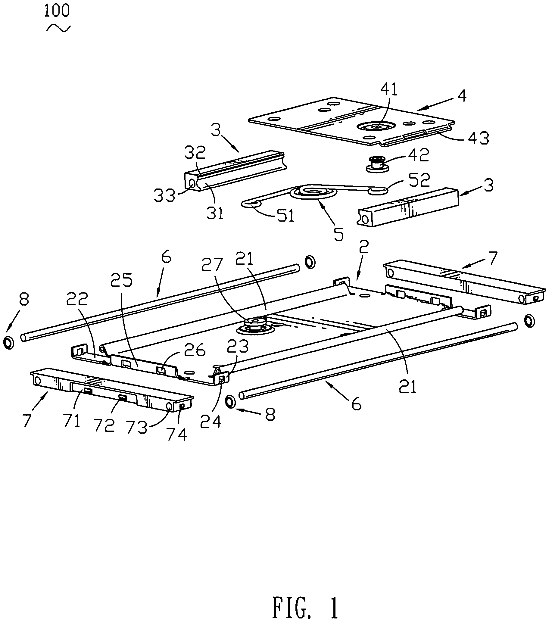
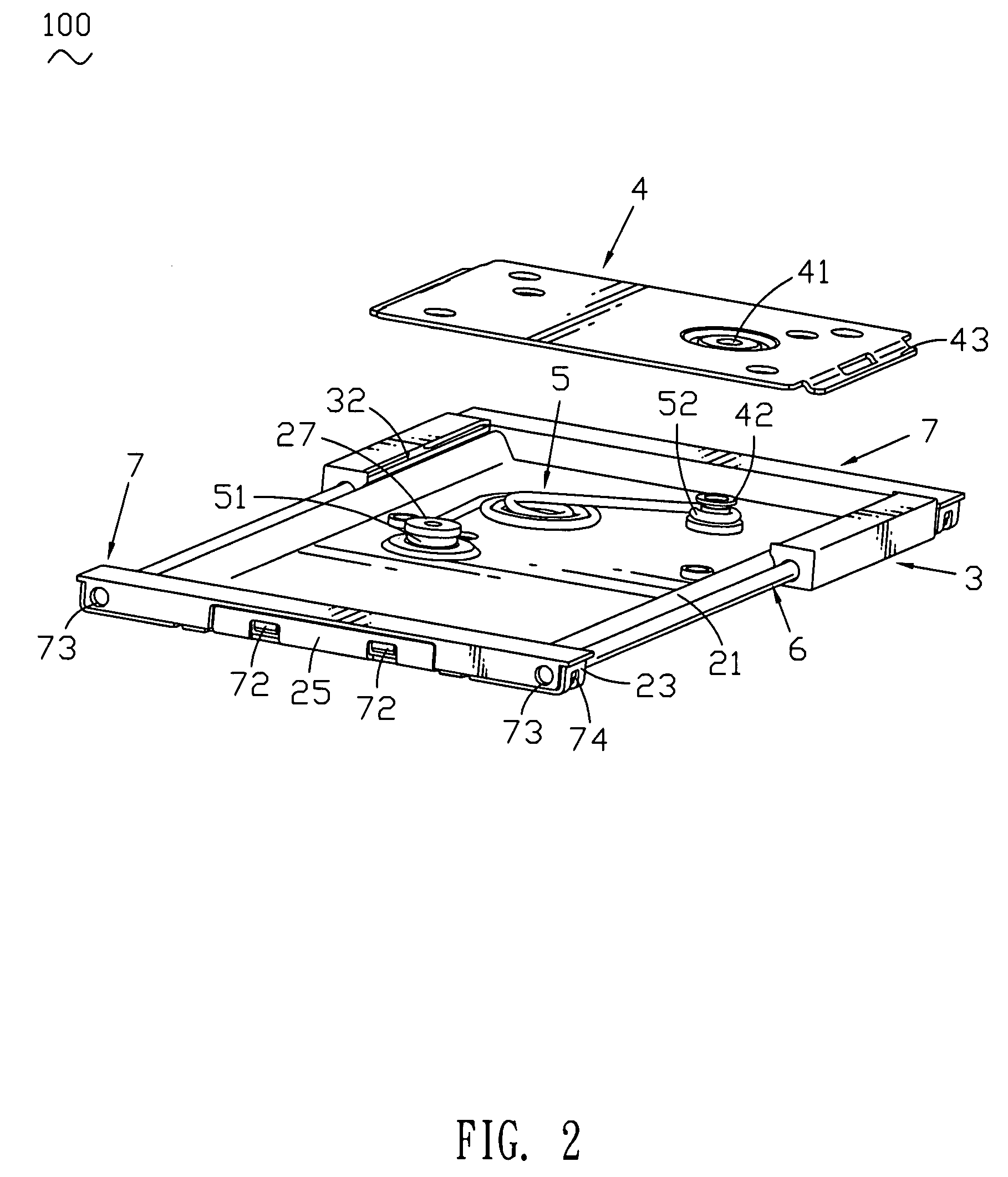
[0017]With reference to FIG. 1, a slide module 100 for a slide type electronic device mainly includes a slide base 2 fixed to an upper housing of a slide type electronic device (not shown), a pair of slide rails 3 along which the slide base 2 slides, a slide tray 4 located between the slide rails 3 and fixed to a lower housing, and a torsion spring 5.

[0018]Please refer to FIG. 1 again, the slide base 2 is a rectangular-shaped plate and has two parallel side edges and two opposite ends. Each side edge of the slide base 2 curls inside to form a longitudinal roll edge 21. The front end and the back end of the slide base 2 are the same and face to face with each other. Now take the front end for example, each side of the front end of the slide base 2 extends outward to form a supporting arm 22. The end edge of the supporting arm 22 bends upward to define a buckling portion 23. The buckling portion 23 has a buckling hole 24 defined therein. The central portion of the front end of the sli...


PUM


Abstract

A slide module for a slide type electronic device includes a slide base having two opposite slide edges curling inside to form two longitudinal roll edges. A pair of slide rails are provided with a pair of slick guide recesses. The guide recess receives one roll edge sliding along the guide recess. A locating recess is defined above the guide recess. A guide hole is defined in the slide rail passing therethrough. A slide tray defines a pair of fixed blades located in the locating recesses respectively at two sides thereof. A torsion spring has two free ends. The first end is connected to the slide base and the second end is connected to the slide tray. A pair of guide rods are inserted in the guide holes respectively and equipped in both sides of the slide base. The guide rod slides along the guide hole.

Description

BACKGROUND OF THE INVENTION[0001]1. Field of the Invention[0002]The present invention relates to a slide module, and more particularly to a slide module installed in a slide type electronic device to enable an upper housing to slide on a lower housing.[0003]2. The Related Art[0004]Recently, a lot of portable electronic devices such as portable phones have become popular in our society. Various types of portable electronic devices such as, a bar type, a flip type, a folder type, etc. are manufactured to satisfy different people.[0005]A bar type electronic device, since its keypad is exposed, can easily be damaged or the keypad can be pressed by mistake. A flip type electronic device is introduced to solve the problem by a provided flip to protect the keypad. However, it still remains the same problem, which the bar type electronic device has, that the housing size of the electronic device itself is too long to carry conveniently. Further, the flip type electronic device fails to sati...

Claims


Application Information

Patent Timeline
Patent Type & Authority Patents(United States)
IPC IPC(8): H04M1/00H04M9/00
CPCH04M1/0237
Inventor LIN, JUI-PINYIN, TE-HUNG
Owner CHENG UEI PRECISION IND CO LTD
Learn More