Airbag unit

a technology for airbags and units, which is applied in the direction of pedestrian/occupant safety arrangements, vehicular safety arrangments, vehicle components, etc., can solve the problems of difficult sealing of the outlet valve and complicated manufacturing of the outlet valve, and achieve the effect of reducing the effective outlet cross-section, convenient folding, and reliable operation

Active Publication Date: 2010-01-26
AUTOLIV DEV AB
View PDF9 Cites 52 Cited by
  • Summary
  • Abstract
  • Description
  • Claims
  • Application Information

AI Technical Summary

Benefits of technology

[0011]According to the invention, the outlet valve is constructed as follows: a fabric nozzle extends round an opening in the airbag wall, and the second tensioning element, which extends directly or indirectly to the impact surface, is guided around this fabric nozzle, so that when pulling takes place it draws the fabric nozzle together and therefore reduces the effective outlet cross-section or even closes it completely. Such an outlet valve can easily be folded and it is not necessary that the element which closes the opening is supported against the airbag wall when it closes. This achieves reliable functioning.

Problems solved by technology

Such an outlet valve is complicated to manufacture and it must be ensured that the outlet valve remains functional when the airbag deploys.
A particular disadvantage here, is that it is difficult to achieve sealing of the outlet valve, as the fabric tab has to be moved against the internal pressure of the airbag, and the airbag wall against which the fabric tab is supported is naturally made of flexible woven material.

Method used


Image

  • Airbag unit
  • Airbag unit
  • Airbag unit

Examples


first embodiment

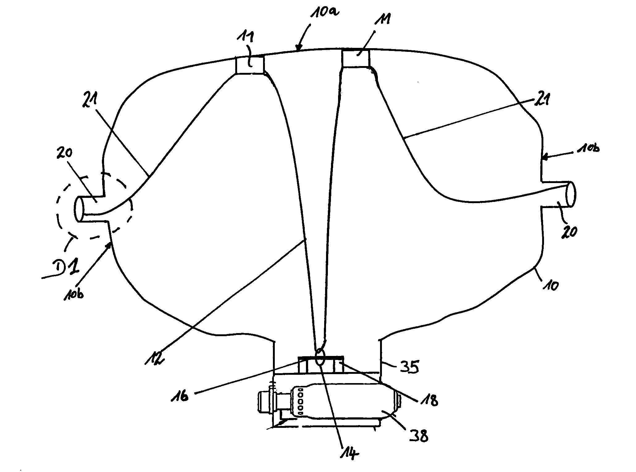
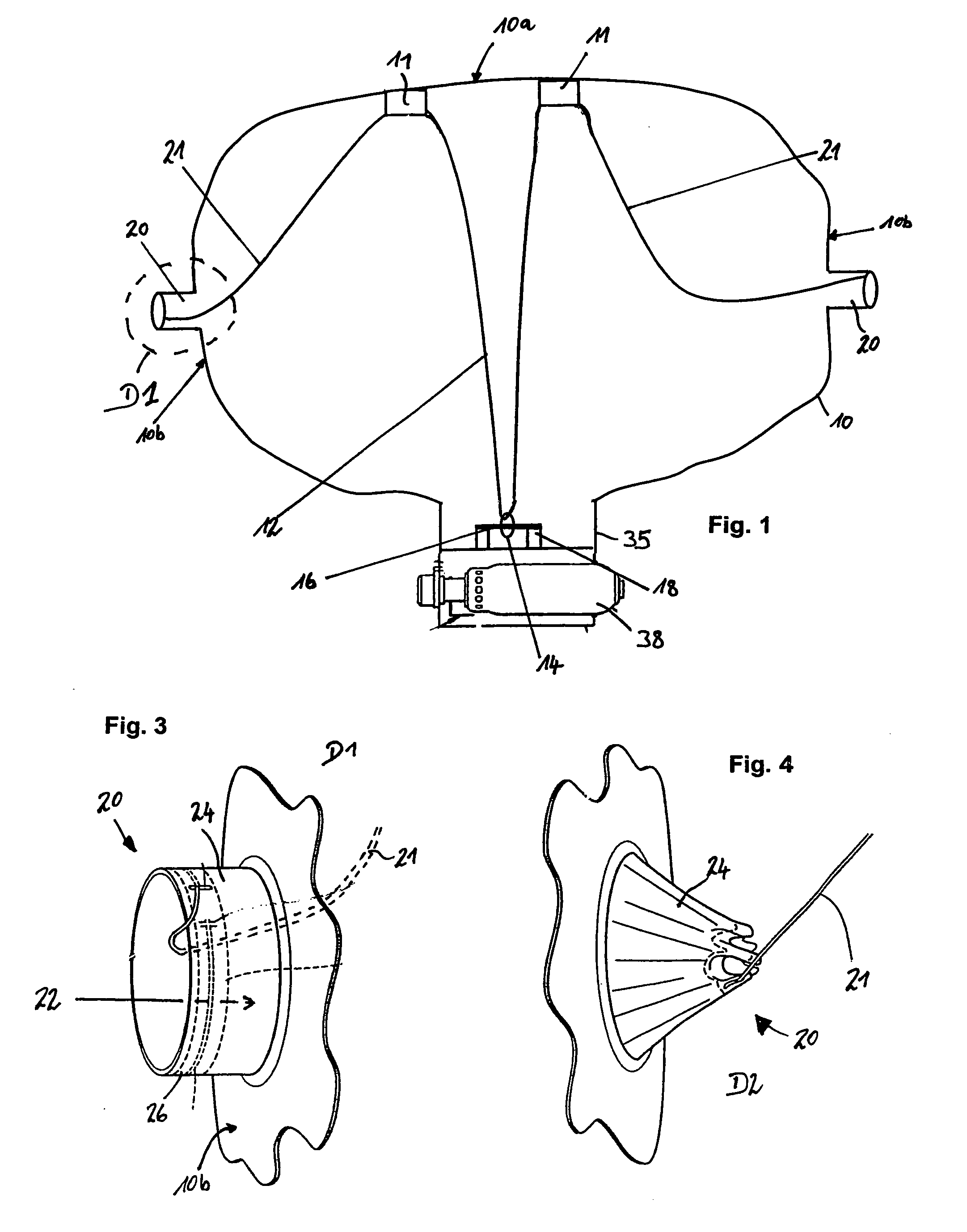
[0027]At the position at which an outlet valve 20 is situated, side surface 10b of airbag 10 exhibits an opening 22. From the edge of this opening 22, a nozzle 24 consisting of fabric extends. This nozzle is of annular shape when outlet valve 20 is open as shown in FIG. 3. A tunnel 26 of fabric is provided on the edge of nozzle 24 turned away from the airbag fabric, through which second tensioning thread 21 extends. In the first embodiment shown in FIGS. 3 and 4, the end of the first tensioning thread 12 is connected to the nozzle 24. If as is shown in FIG. 4, second tensioning thread 21 is placed under tension—which occurs when airbag 10 reaches its maximum deployed state—first nozzle 24 is pulled over into the inside of airbag 10 and then pulled together, until the state shown in FIG. 4 is reached. It can be seen that the effective cross-section of outlet valve 20 is then considerably smaller than opening 22. The pressure inside the airbag 10 obstructs the drawing together of the ...

second embodiment

[0031]FIG. 9 shows an airbag unit. Here, the first tensioning element is in the form of a tether 13 with a set break location 13a. This set break location 13a is formed in such a way that tether 13 remains intact if only the first stage of a two-stage gas generator 38 is triggered. However, if the internal pressure in the airbag increases by triggering of the second stage of the gas generator also, the tether tears at set break location 13a and airbag 10 expands to its maximum depth, as described above. Structure and function of outlet valve 20 and its triggering by second tensioning thread 21 is also as described above, so that this does not need to be explained again here. It is also possible to so set up the break location as a tear seam tearing on exceed of a predetermined force. This tear seam can especially be provided at the connection of the tether with the retaining part or with the impact surface. The break location can be provided alternatively or additionally to the poss...


PUM


Abstract

An airbag unit with an airbag exhibiting an impact surface, a housing, a gas generator, a first tensioning element extending from housing to impact surface, which is interrupted when the airbag is fully expanded, and a second tensioning element extending from impact surface to an outlet valve with variable cross section located in airbag. The cross section of the outlet valve becomes smaller when the second tensioning element is under tension. In order to ensure a high degree of functional reliability, outlet valve exhibits a nozzle extending around an opening, around which the second tensioning element is guided.

Description

CROSS-REFERENCE TO RELATED APPLICATIONS[0001]This application is a 371 U.S. National Stage of International Application No. PCT / EP2007 / 003176, filed Apr. 10, 2007 and published in English as WO 2007 / 115818A1 on Apr. 10, 2007. This application claims priority to German Patent Application No. DE 10 2006 017 332.5, filed Apr. 11, 2006, which application is herein expressly incorporated by reference.TECHNICAL FIELD OF THE INVENTION[0002]The invention relates to an airbag unit according to the introductory section of claim 1.[0003]A general task for airbag units, in particular front airbag units, is to supply an expanded airbag for each accident situation and for each vehicle occupant which on the one hand should exhibit sufficient retaining effect and on the other hand should not transfer too high forces into the occupant. The following framework is conditions should basically be taken into consideration in this context: both the seriousness of the accident and the weight of the vehicle...

Claims


Application Information

Patent Timeline
Patent Type & Authority Patents(United States)
IPC IPC(8): B60R21/16B60R21/2338B60R21/2342
CPCB60R21/2338B60R21/239B60R21/2342B60R2021/23382
Inventor BAUBERGER, ALFRED
Owner AUTOLIV DEV AB
Why Eureka
Try Eureka