Coupling for a fluid conducting system

a fluid conducting system and coupling technology, applied in the direction of couplings, pipe elements, mechanical equipment, etc., can solve the problems of insufficient rotational transfer of the coupling part from the locking position into the release position, and the release position exhibits a certain instability, so as to achieve high stability

Active Publication Date: 2010-01-26
A RAYMOND & CO
View PDF21 Cites 20 Cited by
  • Summary
  • Abstract
  • Description
  • Claims
  • Application Information

AI Technical Summary

Benefits of technology

[0006]Through the inventive configuration of the coupling, the movement of the locking part between the release position and the locking position takes place essentially in a linear direction perpendicular to the longitudinal direction of the coupling so that relatively problem-free operation is possible even in narrow spaces. In addition, this results in the advantage that the release position in particular exhibits relatively high stability against the effects of external forces, so that an unintentional snapping of the locking part into the locking position is made more difficult at the least.

Problems solved by technology

When operating the previously known coupling, however, in a certain sense it turned out to be disadvantageous that the release position exhibited a certain instability, since under the effect of a relatively low force on the coupling part, the latter changes over directly from the release position into the locking position in an abrupt fashion.
In addition, the transfer of the coupling part from the locking position into the release position by rotating it has not proven to be optimal because of the relatively large amount of space required for doing this.

Method used


Image

  • Coupling for a fluid conducting system
  • Coupling for a fluid conducting system
  • Coupling for a fluid conducting system

Examples


Embodiment Construction

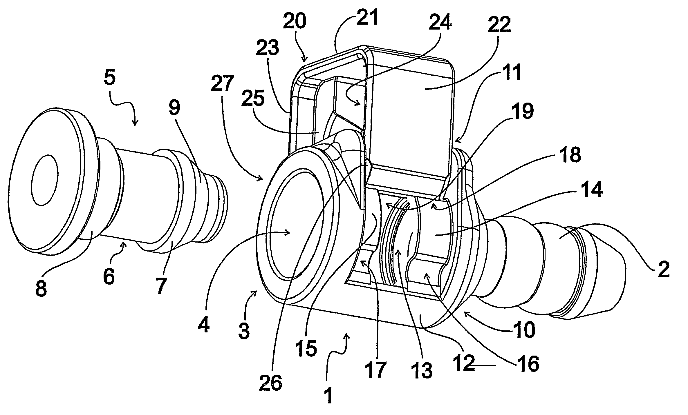
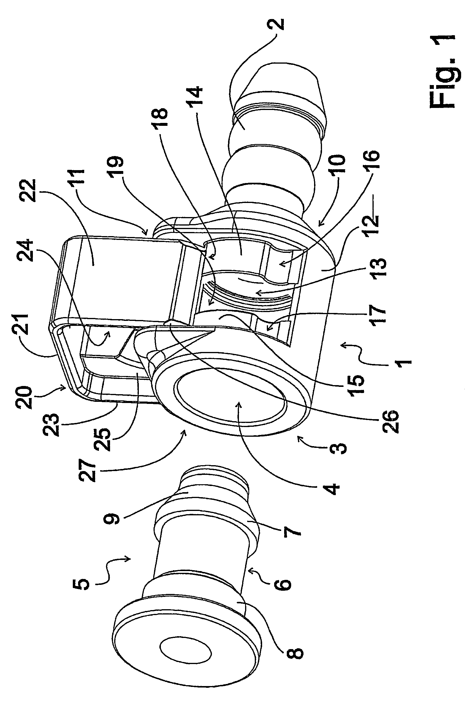
[0012]FIG. 1 shows a perspective view of an embodiment of an inventive coupling, having a elongated coupling part 1 which possesses a connection fitting 2 on one side. A flexible hose of, for example, a fluid conducting system, not shown in FIG. 1, can be slipped onto the connection fitting 2, which is preferably configured with a cross section that varies in the longitudinal direction and is tapered at the end. At an insertions side 3 that is opposite the connection fitting 2, coupling part 1 is configured with an insertion opening 4 that is round in cross section, into which a counterpart, shown in FIG. 1 at a distance from the coupling part 1 and with an elongated, essentially cylindrical insertion section 5, can be inserted.

[0013]The insertion section 5 of the counterpart possesses a circumferential securing recess 6, which is delimited on the edge side by a first edge shoulder 7, which is arranged on the edge side in the region of the free end of the insertion section 5, and a ...


PUM


Abstract

A coupling for a fluid conducting system comprises an elongated coupling part (1) and a locking part (20), which can be displaced in a direction perpendicular to the longitudinal direction and which can be mounted on the coupling part (1) in a manner that enables it to slide. The guiding of the locking part (20) ensues via detent elements (24, 25) that engage inside guide recesses (13) of the coupling part (1). The locking part (20) can be fixed in a releasing position or in a locking position by the engagement of detent projections (26, 27) inside releasing recesses (18, 19) or inside locking recesses (16, 17). This enables a relatively problem-free operating of the coupling during opening and closing.

Description

TECHNICAL FIELD[0001]The invention pertains to a coupling for a fluid conducting system, having a coupling part into which an insertion section of a counterpart can be inserted, and having a locking part which is mounted in movable fashion on the coupling part and which possesses a detent structure which in a detent position interacts with a complementary structure configured on the insertion section for locking the counterpart and the coupling part.BACKGROUND[0002]Such a coupling is known from DE 10141315 C1. The previously known coupling possesses a coupling part into which an insertion section of a counterpart can be inserted. Also present is a C-˜shaped locking part which is mounted on the coupling part so that it can rotate around the longitudinal axis of the coupling. As the detent structure, the locking part possesses sections which are like segments of a circle and which in a detent position interact, through the fact that they engage in recesses configured on the coupling p...

Claims


Application Information

Patent Timeline
Patent Type & Authority Patents(United States)
IPC IPC(8): F16L37/08F16L37/12F16L37/14
CPCF16L37/088F16L37/144F16L37/0885F16L37/12F16L37/14
Inventor FEGER, AXELTREDE, MICHAELUTZ, DANIELKUBEL, MATTHIAS
Owner A RAYMOND & CO
Why Eureka
Try Eureka