Three-dimensional image retainer

a three-dimensional image and retainer technology, applied in the direction of mechanical measuring arrangement, instruments, using mechanical means, etc., can solve the problem of difficult to preserve the image for a prolonged period of time, and achieve the effect of preventing the device operator from uncomfortable feeling

Inactive Publication Date: 2010-02-02
KLEYMAN GENNADY +1
View PDF14 Cites 11 Cited by
  • Summary
  • Abstract
  • Description
  • Claims
  • Application Information

AI Technical Summary

Benefits of technology

[0004]These needs are satisfied by the inventive image retainer. Particularly, the device is provided with a plurality of pins each having a pair of smooth ends that are formed and dimensioned to prevent the device operator from uncomfortable feeling.

Problems solved by technology

While a three dimensional image is easily formed, it is difficult to preserve this image for a prolonged period of time.

Method used


Image

  • Three-dimensional image retainer
  • Three-dimensional image retainer
  • Three-dimensional image retainer

Examples


Embodiment Construction

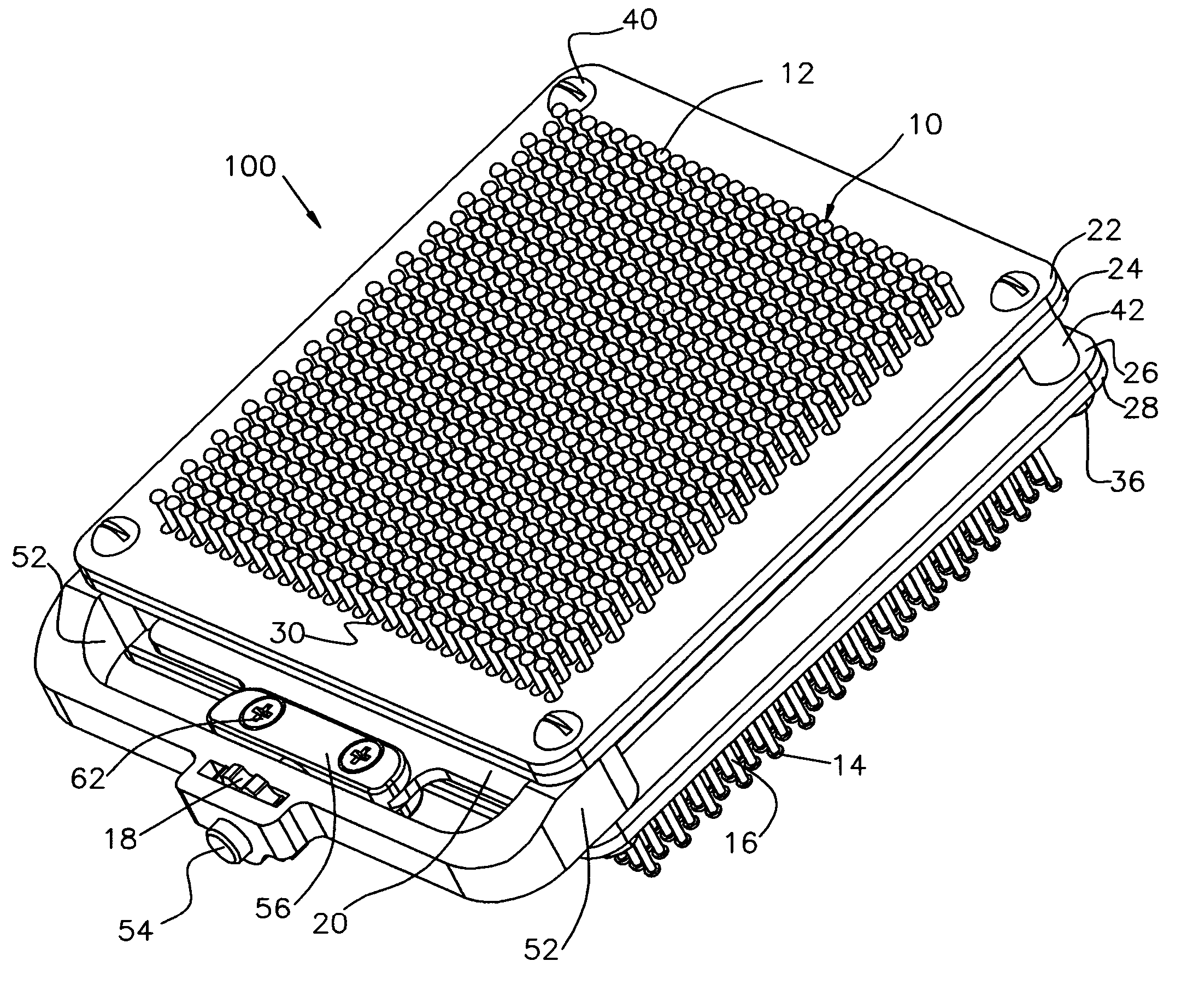
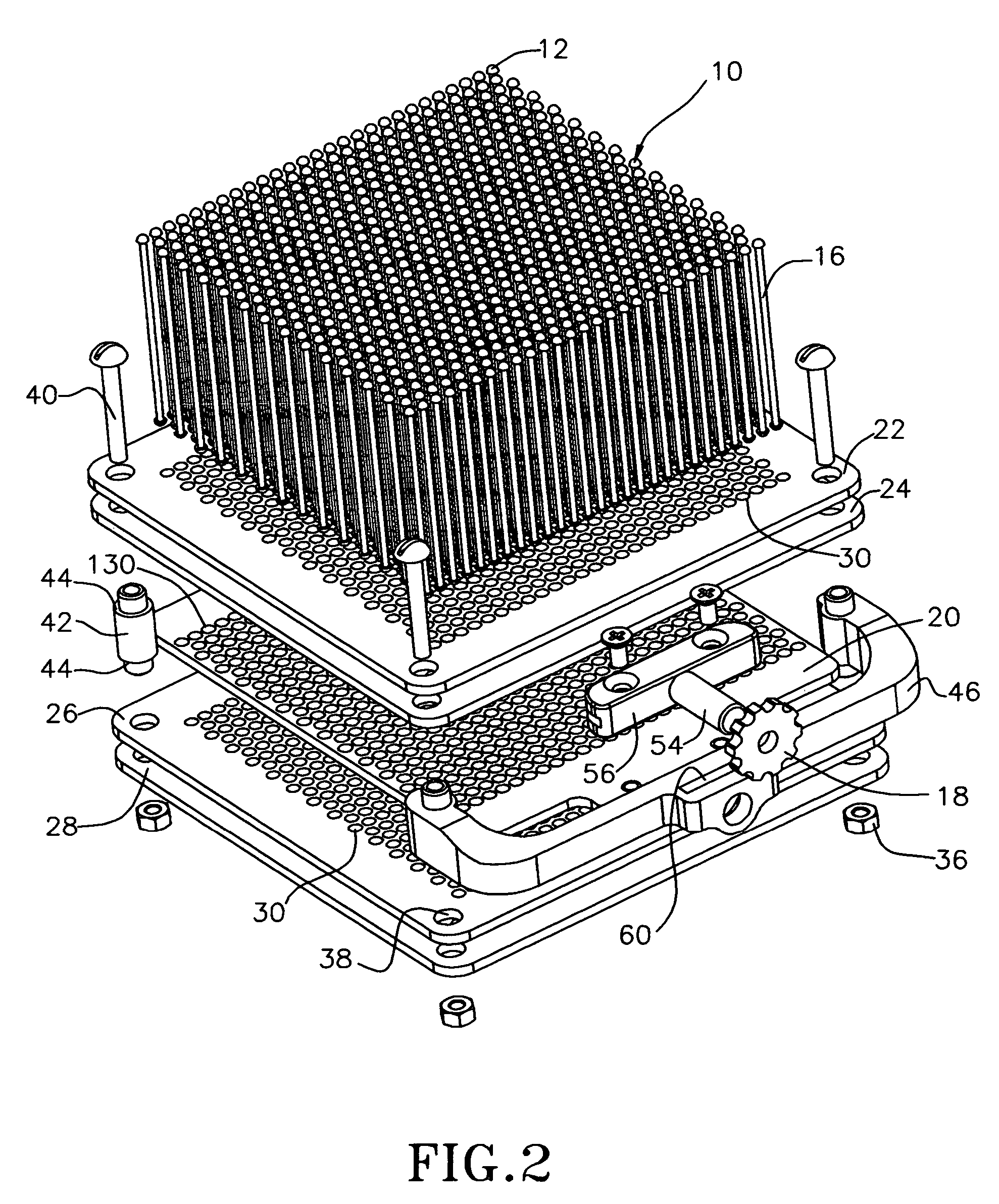
[0029]Referring to FIGS. 1-2, an image retainer 100 is configured to recreate a 3-D image of an object loaded upon either one of opposite enlarged pinhead ends 12, 14 of pins 10 (FIGS. 1-7), which are selectively displaceable in response to a load so as to recreate the 3D image of this load.

[0030]The image retainer 100 includes a plurality of retainer plates 22, 24, 26 and 28 (FIGS. 1, 2) assembled in two pairs and each having a respective multiplicity of openings 30 (FIG. 2). Configuration of the openings is such that the pins 10, each of which has a shank or body 16 provided with fixed or removable pinheads 12, 14 (FIGS. 1-13), can freely move through each of the openings 30, which is dimensioned to have an inner diameter larger than both pin's shank or body 16 and pinheads 12 and 14. The pinheads 12 and 14 each have a smooth, preferably spherical outer surface 34 (FIGS. 6, 7) configured to prevent discomfort or inconvenience that may be experienced by the device operator whose li...


PUM


Abstract

A 3-D image retainer is configured to have a plurality of perforated retainer plates and a retainer assembly displaceable to lock selectively impressed pins, which traverse the retained plates, in the desired position corresponding to the 3-D contour of the applied load.

Description

FIELD OF THE INVENTION[0001]This invention relates to a three-dimensional image retainer.BACKGROUND OF THE INVENTION[0002]It is known to utilize devices capable of forming a three-dimensional image of an object. Typically, these devices are provided with a support and a plurality of pins which can slide through numerous holes formed in the support in response to an external load. Depending on a shape of the load, the pins are displaceable at different distances to form a contour corresponding to a shape of the load. While a three dimensional image is easily formed, it is difficult to preserve this image for a prolonged period of time. Particularly, displacing the support causes the pins to move from a position corresponding to the formed image.[0003]It is therefore desirable to provide a three-dimensional image device which is capable of retaining a contour corresponding to the shape of a load even when the device is displaced.SUMMARY OF THE INVENTION[0004]These needs are satisfied ...

Claims


Application Information

Patent Timeline
Patent Type & Authority Patents(United States)
IPC IPC(8): A47F11/06
CPCG01B5/207
Inventor KLEYMAN, GENNADYCHERNOV, YURLY
Owner KLEYMAN GENNADY
Why Eureka
Try Eureka