Vehicle, control device for vehicle, and control method for vehicle

a technology for controlling devices and vehicles, applied in electric control, machines/engines, transportation and packaging, etc., can solve the problems of giving an uncomfortable feeling to a driver, and the filter cannot be regenerated, so as to reduce the uncomfortable feeling and reduce the uncomfortable feeling

Active Publication Date: 2018-10-04
TOYOTA JIDOSHA KK
View PDF3 Cites 8 Cited by
  • Summary
  • Abstract
  • Description
  • Claims
  • Application Information

AI Technical Summary

Benefits of technology

[0008]The vehicle travels in a mode that is selected from the plurality of modes including the first mode in which the engine is operated at the predetermined load and the second mode in which the engine is operated at the load higher than the predetermined load. When the accumulation quantity of the particulate matter in the particulate matter removal filter attached to the exhaust system of the engine is equal to or more than the threshold, the electronic control unit notifies the driver that traveling in the second mode is recommended. When the driver selects the second mode in response to the notification, the vehicle travels in the second mode in which the engine is operated at the load higher than the predetermined load. Therefore, even when the high-load operation of the engine is performed for the regeneration of the filter, it is possible to restrain the uncomfortable feeling to be given to the driver. Then, when the temperature of the particulate matter removal filter reaches a temperature equal to or higher than the regenerative temperature due to traveling in the second mode, air is supplied to the particulate matter removal filter by increasing air-fuel ratio or performing fuel cut, so that the particulate matter removal filter is regenerated. As a result, it is possible to regenerate the particulate matter removal filter, while restraining the uncomfortable feeling to be given to the driver. Here, the second mode may be a mode in which a commanded power with respect to a depression amount of an accelerator pedal is higher than in the first mode.

Problems solved by technology

However, the high-load operation of the engine for the regeneration of the filter gives an uncomfortable feeling to a driver who usually operates the engine only at a relatively low load, because of impairing a usual silence.
In this case, when the silence is kept, the filter cannot be regenerated.

Method used


Image

  • Vehicle, control device for vehicle, and control method for vehicle
  • Vehicle, control device for vehicle, and control method for vehicle
  • Vehicle, control device for vehicle, and control method for vehicle

Examples


Embodiment Construction

[0020]Hereinafter, modes for carrying out the disclosure will be described with use of embodiments.

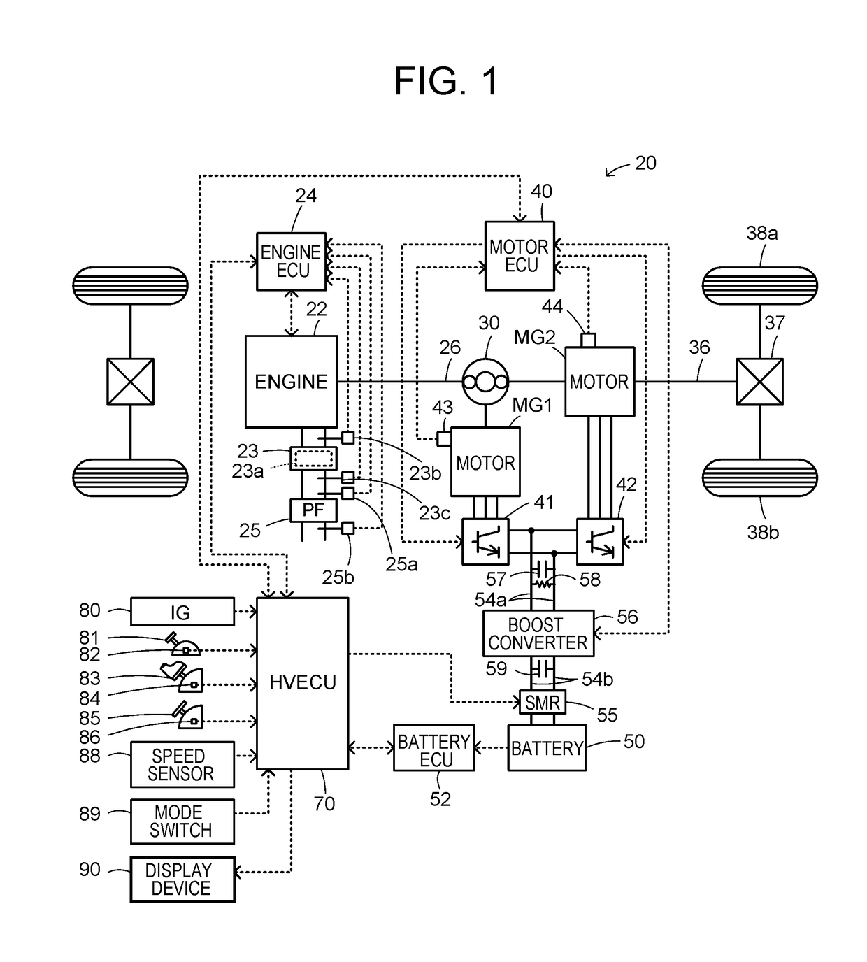
[0021]FIG. 1 is a configuration diagram showing a schematic configuration of a hybrid vehicle 20 in a first embodiment of the disclosure. As illustrated, the hybrid vehicle 20 in the embodiment includes an engine 22, an electronic control unit for the engine (hereinafter, referred to as an engine ECU) 24, a planetary gear 30, a motor MG1, a motor MG2, inverters 41, 42, an electronic control unit for the motors (hereinafter, referred to as a motor ECU) 40, a battery 50, an electronic control unit for the battery (hereinafter, referred to as a battery ECU) 52, a boost converter 56, and an electronic control unit for the hybrid vehicle (hereinafter, referred to as an HVECU) 70.

[0022]The engine 22 is configured as an internal combustion engine that outputs dynamic power using gasoline, light oil or the like as fuel. The operation of the engine 22 is controlled by the engine ECU 24. An exha...


PUM


Abstract

A vehicle includes an engine having a particulate matter removal filter to remove particulate matter, in an exhaust system, and a control device to control the engine such that the vehicle travels in a mode selected from a plurality of modes including a first mode in which both fuel efficiency and ride quality are achieved and a second mode in which the engine is operated at a load higher than a predetermined load. When an accumulation quantity of the particulate matter in the particulate matter removal filter is equal to or more than a threshold, the control device notifies a driver that traveling in the second mode is recommended. When the driver selects the second mode in response to the notification, it is possible to restrain an uncomfortable feeling to be given to the driver, even if the engine is operated at a high load for regenerating the filter.

Description

INCORPORATION BY REFERENCE[0001]The disclosure of Japanese Patent Application No. 2017-064704 filed on Mar. 29, 2017 including the specification, drawings and abstract is incorporated herein by reference in its entirety.BACKGROUND1. Technical Field[0002]The disclosure relates to a vehicle, and specifically, relates to a vehicle including an engine having a particulate matter removal filter to remove particulate matter, in an exhaust system, a control device for the vehicle, and a control method for the vehicle.2. Description of Related Art[0003]As this kind of vehicle, conventionally, there has been proposed a vehicle that includes a filter to remove particulate matter (PM), in an exhaust system, and that secures engine operating time necessary for rise in the temperature of the filter, to quickly regenerate the filter (for example, Japanese Patent Application Publication No. 2015-202832). The vehicle includes an electric storage device that is charged when the engine operates. When...

Claims


Application Information

Patent Timeline
Patent Type & Authority Applications(United States)
IPC IPC(8): F02D41/02B60W30/182B60W10/08B60W10/06B60W10/30B60W50/08B60W50/14B60W20/16
CPCF02D41/024B60W30/182F02D41/029B60W10/08B60W10/06B60W10/30B60W50/082B60W50/14B60W20/16B60W2530/12B60Y2300/476B60W2050/146F02D2041/026B60W20/15F01N3/021B60W2710/083B60W2710/0666B60W2540/10B60W2520/10F02D41/22F02D2041/228F02D2200/0812Y02T10/84Y02T10/12Y02T10/62
Inventor HIGA, MITSUAKISUGAI, SHINICHIITOYAMA, DAISUKEMIGITA, TSUBASAMATSUMURA, MITSUYORI
Owner TOYOTA JIDOSHA KK
Why Eureka
Try Eureka