Vehicle air conditioner with variable displacement compressor

a compressor and variable-discharge technology, which is applied in the direction of machines/engines, positive-discharge liquid engines, light and heating apparatus, etc., can solve the problems of fluctuation of power torque of the engine driving the compressor, the compressor displacement control in the compressor is a problem, and the cooling or dehumidification operation cannot be favorable, so as to achieve effective cooling and dehumidification operations

Inactive Publication Date: 2007-04-19
DENSO CORP
View PDF6 Cites 10 Cited by
  • Summary
  • Abstract
  • Description
  • Claims
  • Application Information

AI Technical Summary

Benefits of technology

[0008] The invention has been made with the above problems taken into account. A first object of the present invention is to provide a vehicle air condit

Problems solved by technology

However, the displacement control in the compressor in a vehicle air conditioner involves a problem.
In cases where the value of the control current is determined without taking into account delay in the start of operation of the electromagnetic valve, when the flow amount requirement for the compressor is low, the piston of the compressor remains resting, and cooling or dehumidifying ope

Method used


Image

  • Vehicle air conditioner with variable displacement compressor
  • Vehicle air conditioner with variable displacement compressor
  • Vehicle air conditioner with variable displacement compressor

Examples


first embodiment

(First Embodiment)

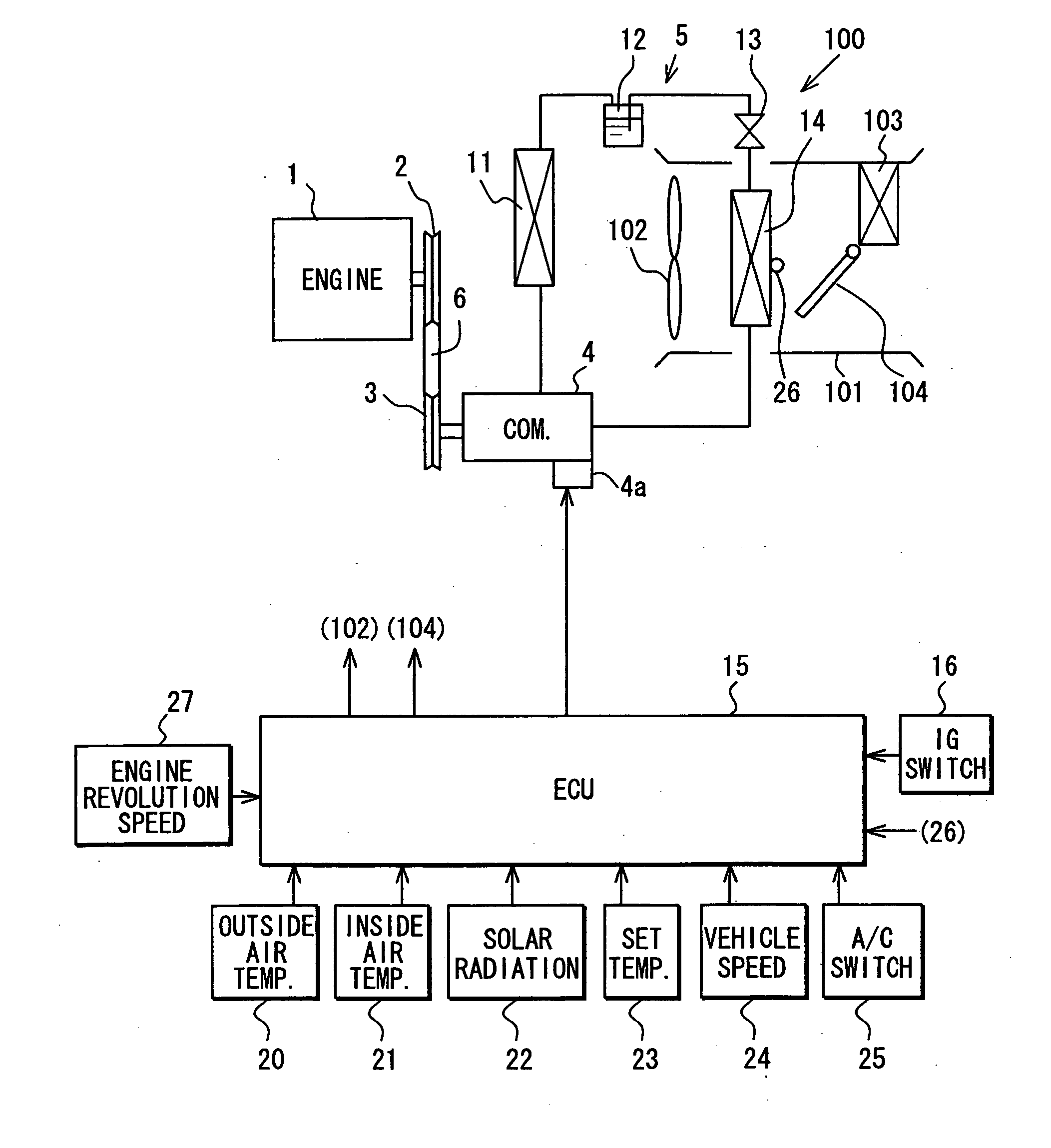
[0027] As illustrated in FIG. 1, an output shaft of an engine 1 is provided with a driving pulley 2. This driving pulley 2 is so constructed that it is rotated in conjunction with driving of the engine 1.

[0028] Around the driving pulley 2 and a driven pulley 3, there is threaded a belt 6 as a power transmission member. A compressor 4 is a variable displacement compressor, that is one of the components of the refrigeration cycle 5 mounted in the relevant vehicle.

[0029] The compressor 4 is not provided with an electromagnetic clutch or the like as a power connecting / disconnecting means, and is constantly driven by the engine 1. The compressor 4 is so constructed that its displacement can be varied substantially within the range of 0 to 100% according to a number of engine revolutions and a cooling load.

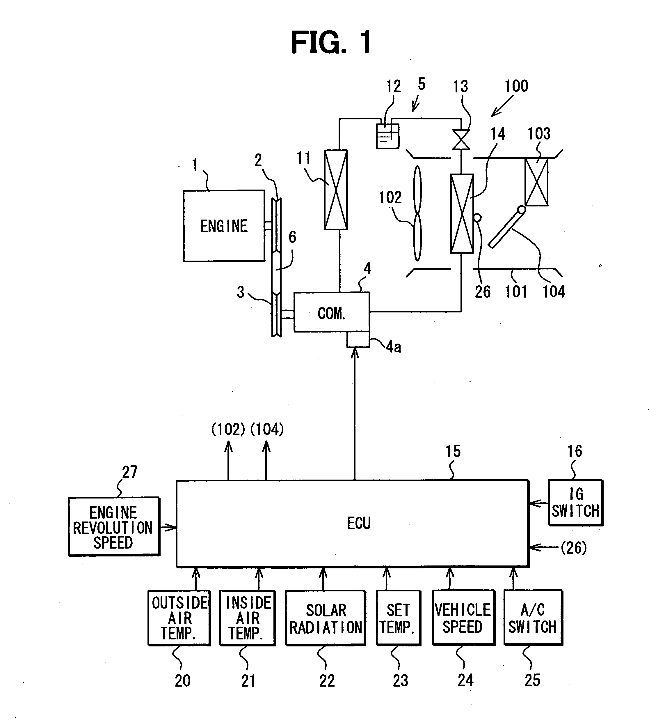
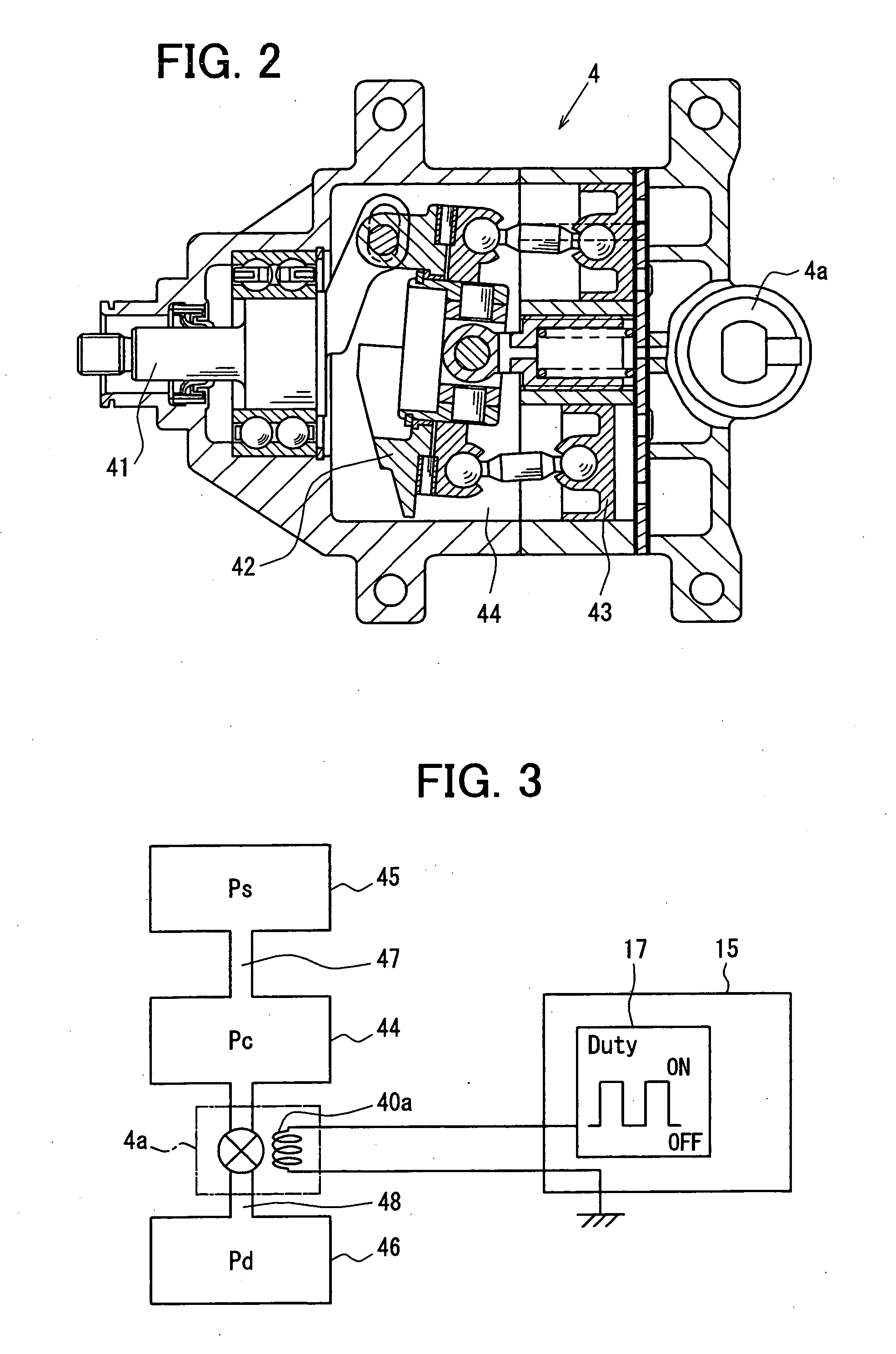
[0030] Brief description will be given to the refrigeration cycle 5 including the compressor 4. As illustrated in FIG. 2, the compressor 4 is a swash plate-type ext...

second embodiment

(Second Embodiment)

[0073] Description will be given to a second embodiment with reference to FIG. 6 to FIG. 8.

[0074] The second embodiment is different from the first embodiment in that a control current value is corrected based on fluctuation in refrigerant discharge pressure. The same members as in the first embodiment will be indicated with the same reference numerals, and the description of them will be omitted.

[0075] Though the description has been omitted with respect to the first embodiment, the refrigeration cycle 5 of the vehicle air conditioner 100 in this embodiment is constructed as illustrated inFIG. 6. In the high-pressure circuit portion running from the discharge side of the compressor 4 to the inlet of the expansion valve 13, there is provided a pressure sensor 18 that is a discharge pressure detecting means for detecting high pressure (compressor refrigerant discharge pressure). In the example illustrated in FIG. 6, the pressure sensor 18 is provided in the refri...


PUM


Abstract

An air conditioner includes a variable displacement compressor that compresses refrigerant from an evaporator and varies a displacement according to a pressure in its control pressure chamber, and an electromagnetic valve that changes an opening such that the displacement of the refrigerant is increased in accordance with an increase in a value of current passing therethrough and changes a pressure state applied into the control pressure chamber. A control unit computes a target cooling temperature of air cooled by the evaporator, and adjusts the value of current passing through the electromagnetic valve to control the displacement so that the air temperature cooled by the evaporator approaches to the target cooling temperature. Furthermore, the control unit sets the value of current passing through the electromagnetic valve at a current value equal to or higher than a predetermined value that is determined based on an operation characteristic of the electromagnetic valve.

Description

CROSS REFERENCE TO RELATED APPLICATION [0001] This application is based on Japanese Patent Application No. 2005-299246 filed on Oct. 13, 2005, the contents of which are incorporated herein by reference in its entirety. FIELD OF THE INVENTION [0002] The present invention relates to a vehicle air conditioner in which a refrigeration cycle is constructed with a variable displacement compressor. More particularly, the present invention relates to a compression device having a variable displacement compressor for a refrigerant cycle system. BACKGROUND OF THE INVENTION [0003] As one of conventional arts, there is a vehicle air conditioner disclosed in JP-2005-104305A (corresponding to US 2005 / 0066669 A1). A compressor adopted in this vehicle air conditioner is an external variable displacement compressor that has an electromagnetic displacement control valve (electromagnetic valve) controlled by electrical signals from a control device and is so constructed that a control pressure is vari...

Claims


Application Information

Patent Timeline
IPC IPC(8): B60H1/00F25B49/00
CPCB60H1/3219B60H2001/3238B60H2001/3251B60H2001/3263B60H2001/3275F04B27/1804F04B2027/1827F04B2027/1854F04B2027/1895F25B2600/023F25B2600/2521
Inventor UMEHARA, AKIRA
Owner DENSO CORP
Why Eureka
Try Eureka