Air induction system having bypass flow control

a technology of air induction system and flow control, which is applied in the direction of electric control, combustion engine, machines/engines, etc., can solve the problems of engine efficiency reduction, engine may have to work harder, and expel additional energy

Inactive Publication Date: 2010-02-02
CATERPILLAR INC
View PDF28 Cites 30 Cited by
  • Summary
  • Abstract
  • Description
  • Claims
  • Application Information

AI Technical Summary

Problems solved by technology

However, by restricting the flow of air into the combustion chamber of the engine, the efficiency of the engine may be reduced.
In particular, when the throttle valve is in a flow-restricting position, the engine may have to work harder (e.g., expel additional energy) to draw or pump in the same amount of air as compared to when the throttle valve is in a non-restricting position.
This additional work output of the engine decreases the efficiency of the engine.
Although the system of the '888 patent may increase the efficiency of an engine, it may be complex, expensive, and still lack optimal efficiency.
In particular, because the system of the '888 patent requires both a compressor bypass and a wastegate, control of the system may be complicated and component cost of the system substantial.
In addition, because the bypass diverts compressed air to the turbine, the energy of the compressed air may either be wasted to the atmosphere via the wastegate, or wastefully directed to driving the turbine for compressing more air.
Further, although the wastegate and bypass valve of the electronic turbocharger control system may decrease the amount of restriction associated with the throttle, the throttle of the '888 system is still used throughout the operating range of the engine to inefficiently regulate the flow of air into the engine.

Method used


Image

  • Air induction system having bypass flow control
  • Air induction system having bypass flow control

Examples


Embodiment Construction

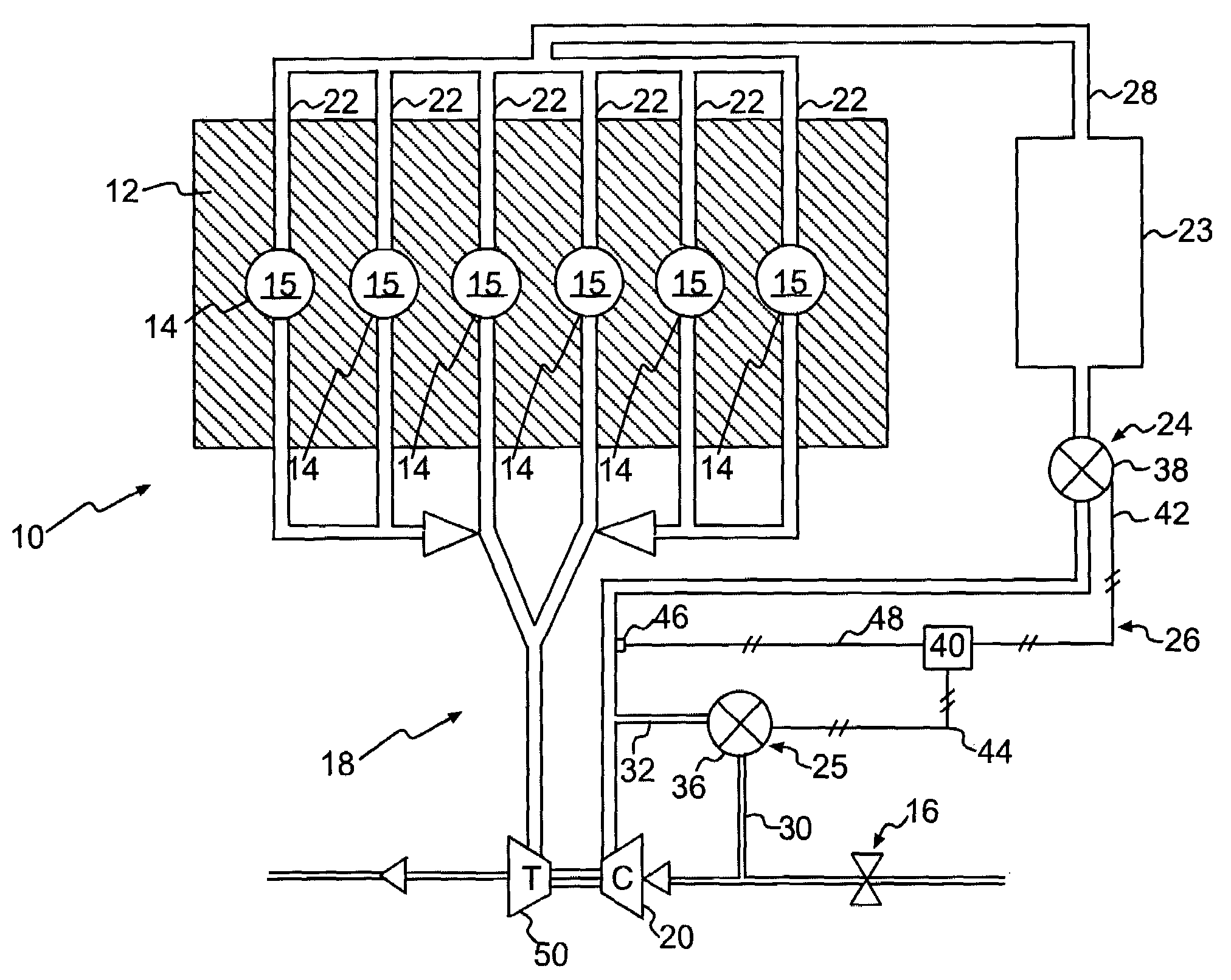
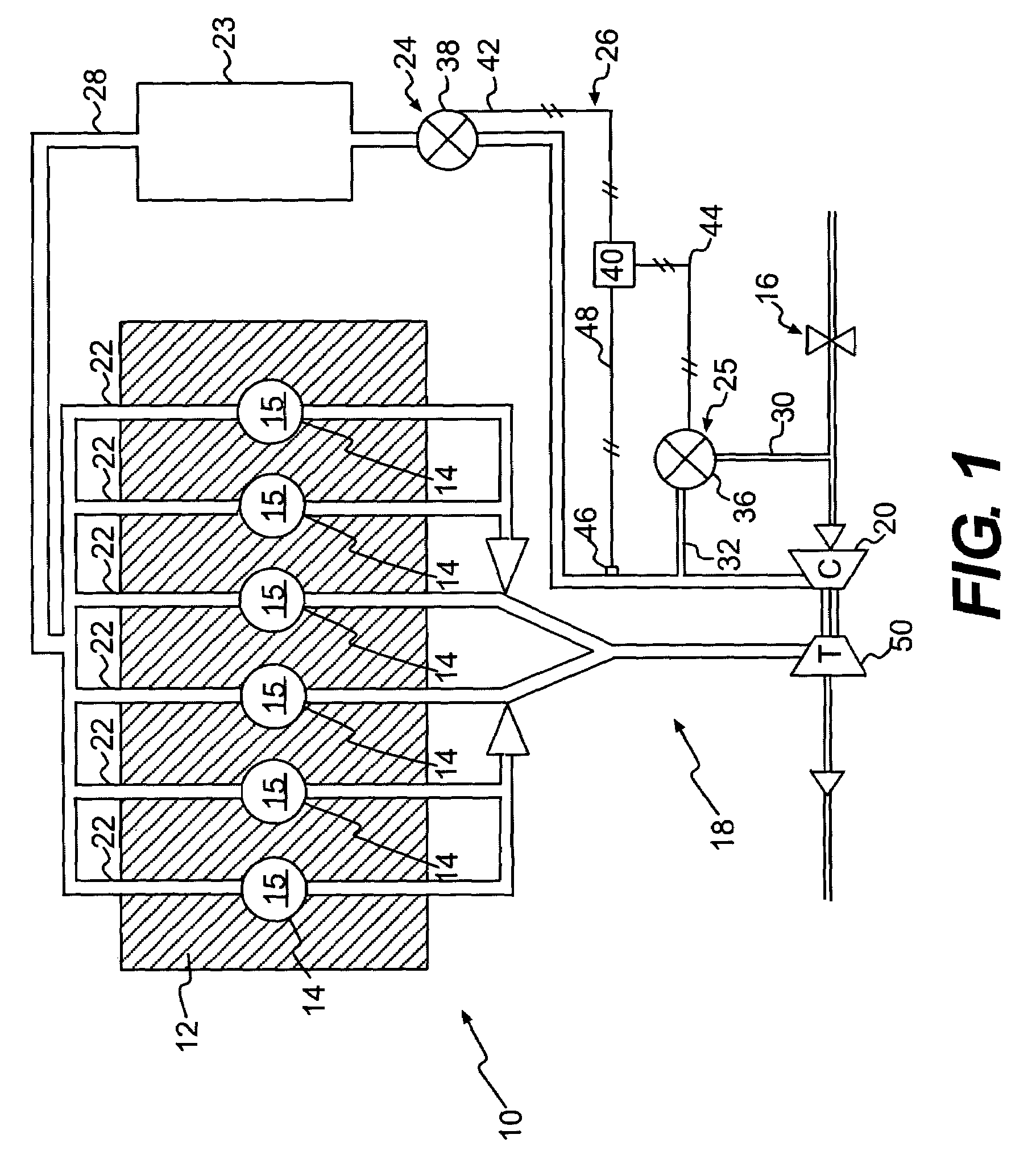
[0011]FIG. 1 illustrates an exemplary disclosed engine 10 having multiple components that cooperate to produce a power output. In particular, engine 10 may include an engine block 12 that defines a plurality of cylinders 14, a piston (not shown) slidably disposed within each cylinder 14, and a cylinder head (not shown) associated with each cylinder 14. It is contemplated that engine 10 may include additional or different components such as, for example, a valve mechanism associated with each cylinder head, one or more fuel injectors, and other components known in the art. For the purposes of this disclosure, engine 10 is depicted and described as a four-stroke gasoline engine. One skilled in the art will recognize, however, that engine 10 may embody any other type of internal combustion engine such as, for example, a gaseous fuel-powered engine.

[0012]The piston, cylinder head, and cylinder 14 may form a combustion chamber 15. In the illustrated embodiment, engine 10 includes six com...


PUM


Abstract

An air induction system for an engine is disclosed. The air induction system has a compressor operable to compress air directed into the engine, a bypass valve, and a throttle valve. The bypass valve may be disposed between the compressor and the engine and may have a valve element movable to selectively divert a portion of the compressed air away from the engine in response to a desired air-to-fuel ratio of the engine. The throttle valve may be disposed between the bypass valve and the engine and may have a valve element movable to selectively restrict the flow of compressed air into the engine in response to a desired air-to-fuel ratio of the engine. The movements of the valve elements of the bypass and throttle valves may be substantially sequential.

Description

TECHNICAL FIELD[0001]The present disclosure relates generally to an air induction system and, more particularly, to an air induction system having bypass flow control.BACKGROUND[0002]Internal combustion engines such as, for example, gasoline engines combust a mixture of air and fuel to produce a power output. The amount of air and fuel and the ratio of air-to-fuel introduced into a combustion chamber of the engine can affect the power output, efficiency, and exhaust emissions of the engine. Typically, the amount of air introduced into the engine and the ratio of air-to-fuel is controlled by a throttle valve mechanism. The throttle valve mechanism selectively restricts the flow of air into the engine to a flow rate that corresponds to a desired ratio of air-to-fuel. However, by restricting the flow of air into the combustion chamber of the engine, the efficiency of the engine may be reduced. In particular, when the throttle valve is in a flow-restricting position, the engine may have...

Claims


Application Information

Patent Timeline
Patent Type & Authority Patents(United States)
IPC IPC(8): F02B33/44F02B37/12F02B37/16
CPCF02B33/34F02B33/44F02B37/16F02D9/02F02D23/00F02D41/0007F02B29/0406F02D11/105Y02T10/144Y02T10/12
Inventor GONG, WEIDONGGODDARD, JOHN D.WILLI, MARTIN L.FIVELAND, SCOTT B.
Owner CATERPILLAR INC
Why Eureka
Try Eureka