
Control apparatus and method for hybrid vehicle

a control apparatus and hybrid technology, applied in the direction of electric devices, gas pressure propulsion mountings, driver input parameters, etc., can solve the problems of reducing the control responsiveness of the opening of the egr valve, deteriorating the drivability, and reducing the rotational speed, so as to improve the fuel efficiency and improve the drivability. , the effect of high egr ra

Active Publication Date: 2010-03-18
TOYOTA JIDOSHA KK
View PDF4 Cites 33 Cited by
  • Summary
  • Abstract
  • Description
  • Claims
  • Application Information

AI Technical Summary

Benefits of technology

[0011]The present invention provides a control apparatus and method for a hybrid vehicle capable of achieving both improvement of fuel efficiency and high drivability by obtaining a high EGR rate.
[0014]According to this invention, both improvement of fuel efficiency and drivability can be suitably achieved by obtaining a high EGR rate.

Problems solved by technology

The problem in increasing the diameter of the EGR pipe or the size of the EGR valve is that the control responsiveness in controlling the opening of the EGR valve is reduced.
Specifically, in a case in which engine stop control is performed in response to a deceleration requirement from a driver, even when a valve closing signal is output to the EGR valve, a predetermined response time period is required until the EGR valve is actually completely closed, due to the impairment in the responsiveness of the EGR valve.
Thus the air-fuel ratio falls out of a combustible mixture ratio, thereby occurring a so-called misfire, which is a phenomenon in which the air-fuel mixture within the combustion chamber is not ignited.
When a misfire occurs, the engine rotational speed decreases, deteriorating the drivability.
Another problem is that there is a negative influence on an exhaust emission control catalyst when unburned air-fuel mixture is discharged to the exhaust passage.

Method used


Image

  • Control apparatus and method for hybrid vehicle
  • Control apparatus and method for hybrid vehicle
  • Control apparatus and method for hybrid vehicle

Examples


Embodiment Construction

[0027]An embodiment of the invention will be described hereinafter in detail with reference to the drawings. Note that the same reference numerals shown in diagrams denote the equivalent or relevant sections.

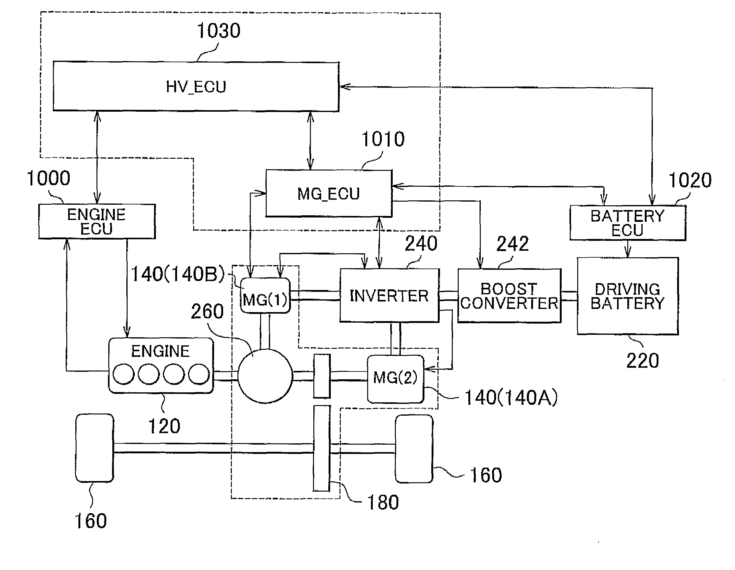
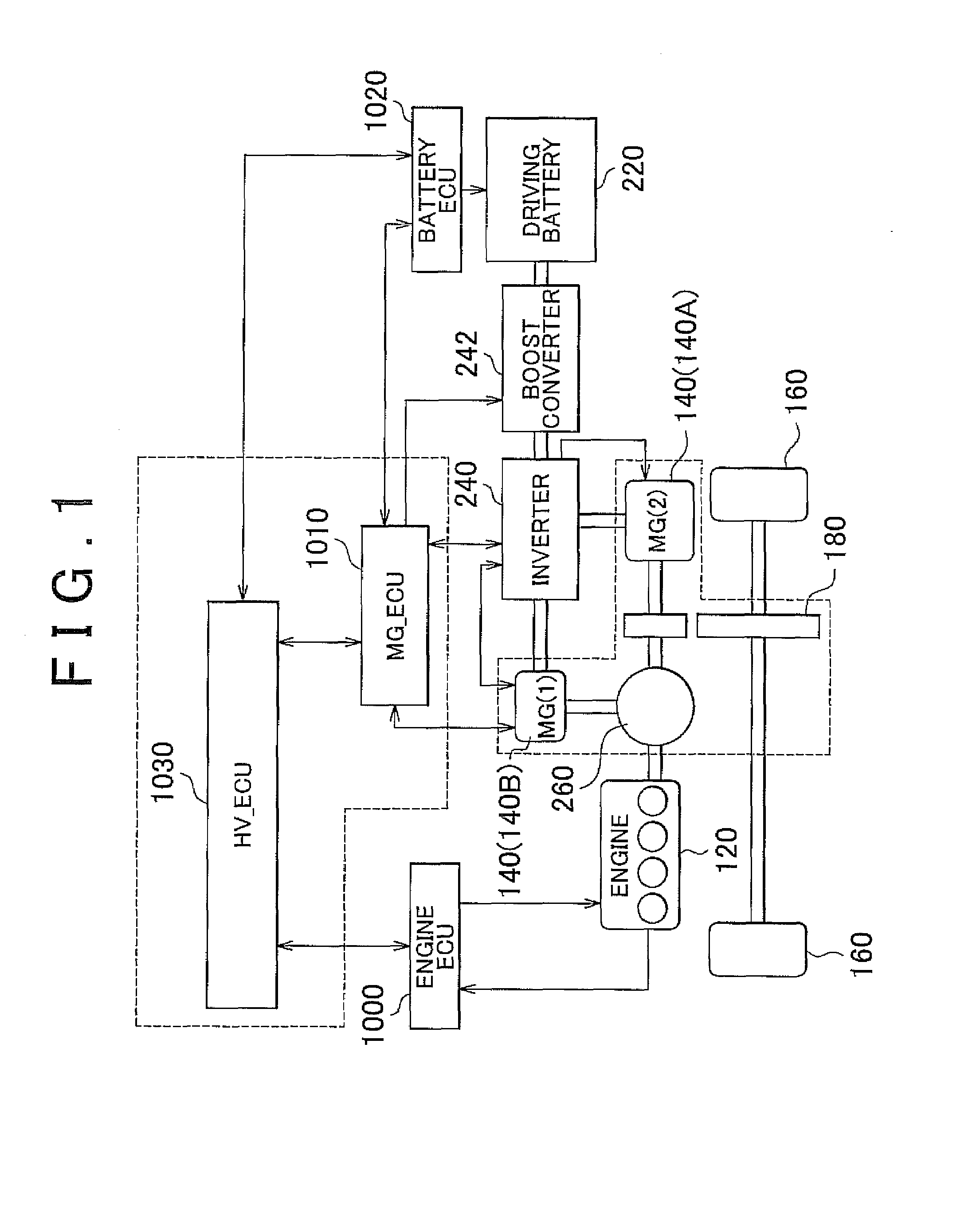
[0028]FIG. 1 is a block diagram for illustrating the configuration of a hybrid vehicle shown as an example of a vehicle installed with a control apparatus according to the embodiment of the invention. Note that the invention is not restricted to the hybrid vehicle shown in FIG. 1.

[0029]The hybrid vehicle has, as the motive power sources, an internal combustion engine (to be referred to as “engine” hereinafter) 120 such as a gasoline engine or a diesel engine, and a MG 140. In FIG. 1, the MG 140 is expressed as a “motor 140A” and a “generator 140B (or “MG 140B”)” for convenience of explanation, as the motor 140A functions as the generator and the generator 140B as the motor, depending on the traveling state of the hybrid vehicle.

[0030]In addition to the MG 140, the hybrid vehicle...


PUM


Abstract

A control apparatus for a hybrid vehicle, which outputs motive power to a drive shaft from an internal combustion engine and motor generators as motive power sources, including: a recirculating gas control portion that performs valve opening control on a recirculation valve so that an amount of recirculating exhaust reaches a control target valve, and that closes the recirculation valve completely when a deceleration request by a driver is detected; a throttle control portion that performs valve closing control on a throttle valve so that the amount of air circulating through an intake pipe decreases at a predetermined speed when the deceleration request issued by the driver is detected; and a braking control portion that controls regenerative braking forces of the motor generators so that at least one of the motor generators absorbs the motive power generated by the engine while valve closing control is executed on the throttle valve.

Description

INCORPORATION BY REFERENCE[0001]The disclosure of Japanese Patent Application No. 2008-239178 filed on Sep. 18, 2008 including the specification, drawings and abstract is incorporated herein by reference in its entirety.BACKGROUND OF THE INVENTION[0002]1. Field of the Invention[0003]The invention relates to a control apparatus and method for a hybrid vehicle, and particularly to a control apparatus and method for a hybrid vehicle having an internal combustion engine and an electric motor as motive power sources.[0004]2. Description of the Related Art[0005]Hybrid vehicles that are driven by efficiently combining an internal combustion engine (engine) and an electric motor (motor) have been practically used in consideration of the environmental problems. As the engine installed in such hybrid vehicles, Japanese Patent Application Publication No. 2008-151064 (JP-A-2008-151064), for example, discloses the engine provided with an exhaust gas recirculation (to be referred to as Exhaust Ga...

Claims


Application Information

Patent Timeline
IPC IPC(8): G06F19/00F02M25/07F02D41/00B60K6/445B60L50/16B60W10/06B60W10/08B60W10/18B60W10/26B60W20/00F02D17/00F02D21/08F02D41/12F02D43/00
CPCB60K6/445B60W10/06B60W10/08B60W20/00B60W30/18127B60W2540/10Y02T10/47F02D41/0005F02D41/005F02D41/12Y02T10/6239Y02T10/6286Y02T10/42B60W2710/0605B60L7/18B60L15/2009B60L15/2054B60L2240/12B60L2240/14B60L2240/441B60L2240/443B60L2240/461B60L2240/485B60L2240/545B60L2250/26B60L2260/26B60L2260/44B60L2270/12B60L2240/50B60L50/61B60L50/16B60L58/15Y02T10/40Y02T10/62Y02T10/70Y02T10/64Y02T10/7072Y02T10/72B60W2510/0609B60W10/24B60W10/18B60W2510/244B60W20/13
Inventor NIIMI, KUNIAKI
Owner TOYOTA JIDOSHA KK
Learn More