
Crayon sharpener

a crayon and pencil technology, applied in the field of crayon sharpeners, can solve the problems of not being able to replicate the factory molded tip of a newly purchased crayon, the tip of a crayon that has been sharpened to a point with prior art devices quickly deteriorates with use into an undesirable and disappointing dull shape,

Active Publication Date: 2010-02-02
SANFORD LP
View PDF28 Cites 14 Cited by
  • Summary
  • Abstract
  • Description
  • Claims
  • Application Information

AI Technical Summary

Benefits of technology

"The present invention provides a system for sharpening crayons using a blade cartridge with a cone-shaped axial bore and a rotary blade with chopping teeth and a smooth cutting edge. The system includes a mechanical device for sharpening crayons that includes an electric motor and a blade cartridge. The method involves inserting the crayon into the blade cartridge, applying force to the crayon, and rotating the blade cartridge to score the paper wrapped around the crayon with the chopping teeth and the smooth cutting edge. The system and method provide a convenient and efficient way to sharpen crayons."

Problems solved by technology

While being generally effective for their intended purpose, currently available crayon sharpeners suffer from certain performance-related shortcomings.
For example, currently available devices are not typically capable of replicating the factory molded tip found on newly purchased crayons.
The tips of crayons that have been sharpened to a point with prior art devices quickly deteriorate with use into an undesirable and disappointing dull shape.
If this paper is not removed, the crayon may not be sharpened at all or the sharpening edges of the sharpener may be quickly dulled.
Finally, when the sharpening edges found in most prior art devices wear and become dull, the sharpening edges and / or blades cannot be easily sharpened or replaced.

Method used


Image

  • Crayon sharpener
  • Crayon sharpener
  • Crayon sharpener

Examples


first embodiment

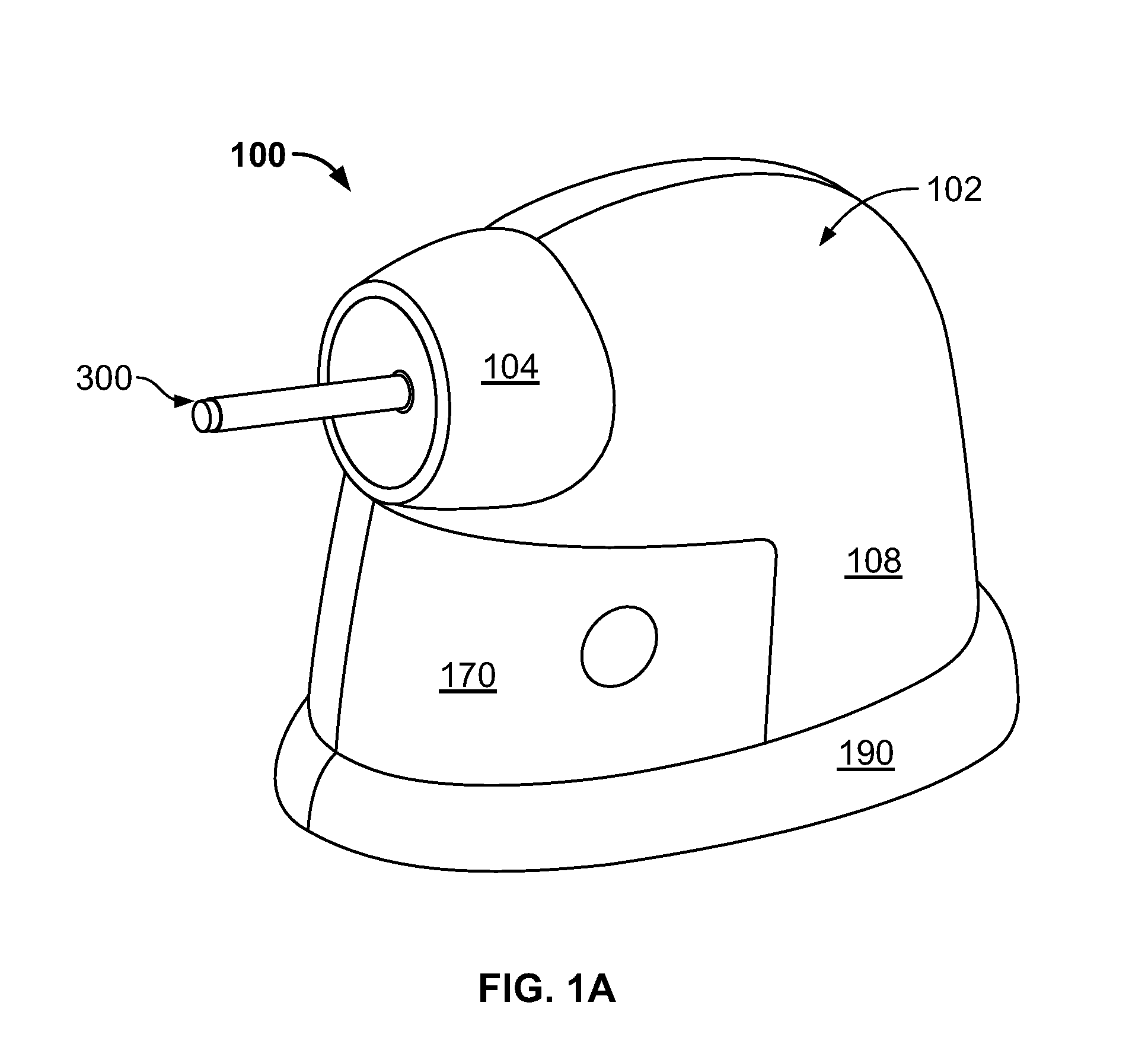
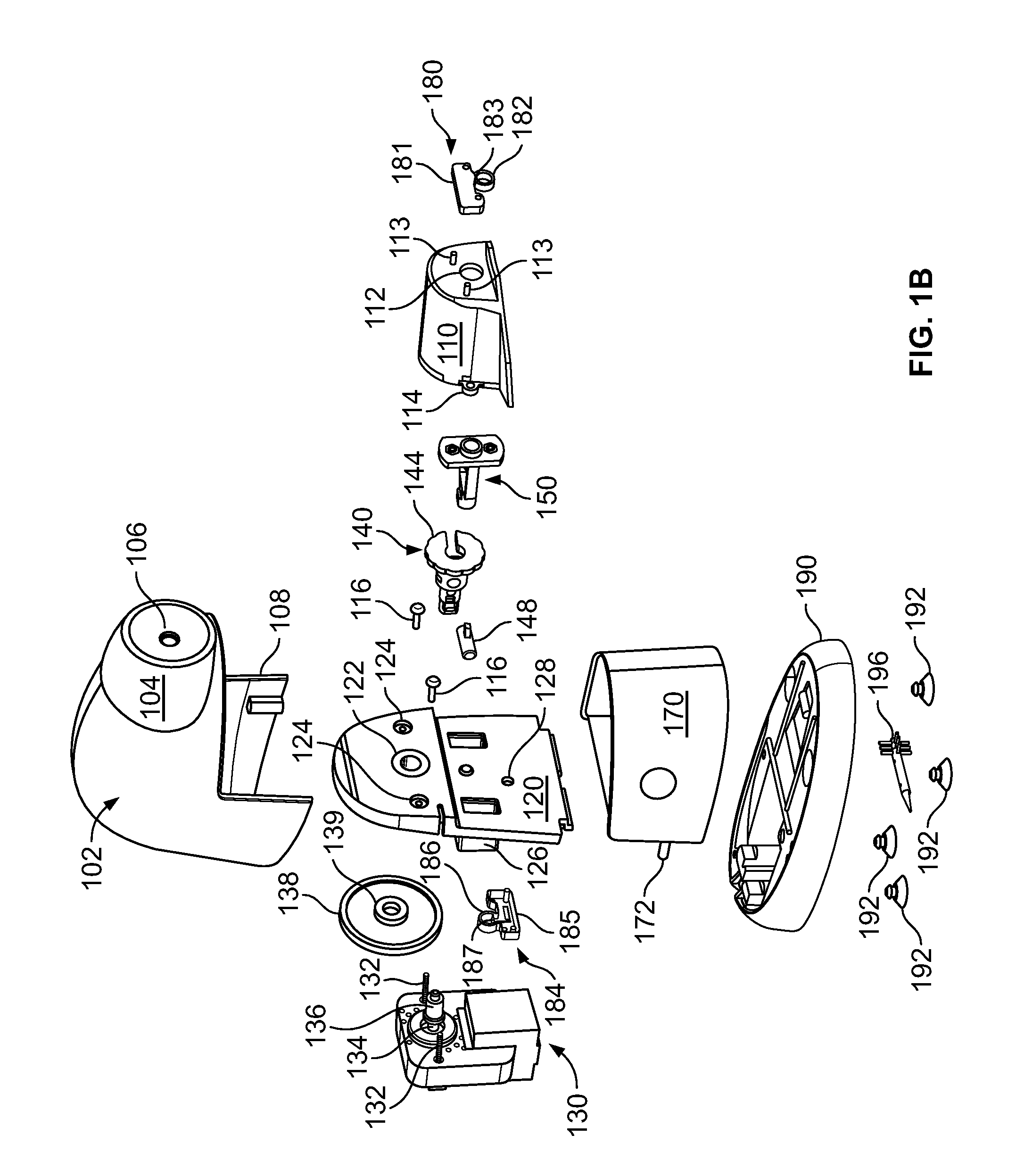
[0028]FIGS. 1A-M provide various illustrative views of the present invention including and include detailed views of certain components thereof. This “front-loading” embodiment is designed to be a heavy-use or high-volume device for schools, businesses, or other institutions. As best shown in FIG. 1A, an assembled sharpener 100 includes a contoured external housing 102 that further includes front portion 104 and bottom portion 108. Aperture 106 is formed in front portion 104 for receiving crayon 300 and bottom portion 108 is shaped to accommodate receptacle 170, which holds crayon shavings and paper fragments. External housing 102 is attached to base 190 and encloses internal components, which include an electric motor, two activation / deactivation safety switches, an adapter, and a removable and replaceable blade cartridge which is mounted on the adapter. A plurality of non-skid (e.g., rubberized or suction cup) feet is typically attached to the bottom surface of base 190 for securi...

second embodiment

[0035]FIGS. 2A-D provide various illustrative views of the present invention including and include detailed views of certain components thereof. This “top-loading” embodiment is designed to be a light-use or relatively low-volume device for home use. As best shown in FIG. 2A, a completely assembled sharpener 200 includes a contoured external housing 202 that further includes top portion 204 and bottom portion 208. Aperture 206 is formed in top portion 204 for receiving crayon 300 and bottom portion 208 is shaped to accommodate receptacle 270, which holds crayon shavings and paper fragments. External housing 202 is attached to base 290 at housing mounts 291 and encloses internal components, which include an electric motor, two activation / deactivation switches, and a blade cartridge. A plurality of non-skid (e.g., rubberized or suction cup) feet is typically attached to the bottom surface of base 290 for securing the crayon sharpener on a surface such as a tabletop or desktop.

[0036]FI...


PUM

PropertyMeasurementUnit
lengthaaaaaaaaaa
angleaaaaaaaaaa
mechanicalaaaaaaaaaa

Abstract

A device for sharpening crayons, wax pencils, and the like is provided. This device includes: a multi-blade removable and replaceable crayon sharpening cartridge; an electric motor mechanically coupled to the blade cartridge for axially rotating the blade cartridge around a crayon that has been inserted into the blade cartridge; a base for supporting the electric motor; a contoured receptacle positionable on the base beneath the blade cartridge for capturing crayon debris; and a contoured exterior housing for enclosing the electric motor and the blade cartridge.

Description

CROSS-REFERENCE TO RELATED APPLICATIONS[0001]This patent application claims the benefit of U.S. Provisional Patent Application Ser. No. 60 / 820,375 filed on Jul. 26, 2006 and entitled “Powered Sharpener for Crayons,” the disclosure of which is incorporated by reference as if fully rewritten herein.BACKGROUND OF THE INVENTION[0002]The described invention relates in general to systems and devices for sharpening writing instruments, and more specifically to an electric crayon sharpener that replicates the general appearance of a factory molded crayon prior to the use thereof.[0003]Devices for sharpening writing instruments such as crayons typically include a cone-shaped tapered channel for receiving a unsharpened crayon. The inner wall of this tapered interior channel usually includes a sharpening edge, which may be formed in the wall of the channel or may be provided as a protruding blade that extends from the opening of the channel to the terminal apex thereof. With regard to manual s...

Claims


Application Information

Patent Timeline
Patent Type & Authority Patents(United States)
IPC IPC(8): B26D1/00
CPCB43L23/008B43L23/02Y10T83/04
Inventor PARRISH, MICHAELSCHUMACHER, MICHAEL
Owner SANFORD LP
Learn More