Electric vehicle

a technology of electric vehicles and cell components, applied in the direction of vehicle sub-unit features, cell components, propulsion by batteries/cells, etc., can solve the problem that the electric components of laminated cell elements cannot be easily short-circuited, and achieve the effect of lowering the cell breakage degr

Inactive Publication Date: 2010-02-02
MITSUBISHI MOTORS CORP
View PDF31 Cites 89 Cited by
  • Summary
  • Abstract
  • Description
  • Claims
  • Application Information

AI Technical Summary

Benefits of technology

[0010]The object of the present invention is to provide an electric vehicle configured so that the degree of breakage of cells can be lowered against a load that is laterally applied to a vehicle body.
[0012]According to this arrangement, if a part of the vehicle body is deformed toward the battery unit by a collision load that is laterally applied to the vehicle body so that sidewalls of the tray member of the battery case and the like are deformed, the cells are pushed in the lamination direction of the cell elements. Even if the cells are pushed in the lamination direction, electrodes of the laminated cell elements cannot be easily short-circuited. Thus, the degrees of breakage and heat generation can be lowered.

Problems solved by technology

Even if the cells are pushed in the lamination direction, electrodes of the laminated cell elements cannot be easily short-circuited.

Method used


Image

  • Electric vehicle
  • Electric vehicle
  • Electric vehicle

Examples


Embodiment Construction

[0027]One embodiment of the present invention will now be described with reference to FIGS. 1 to 11.

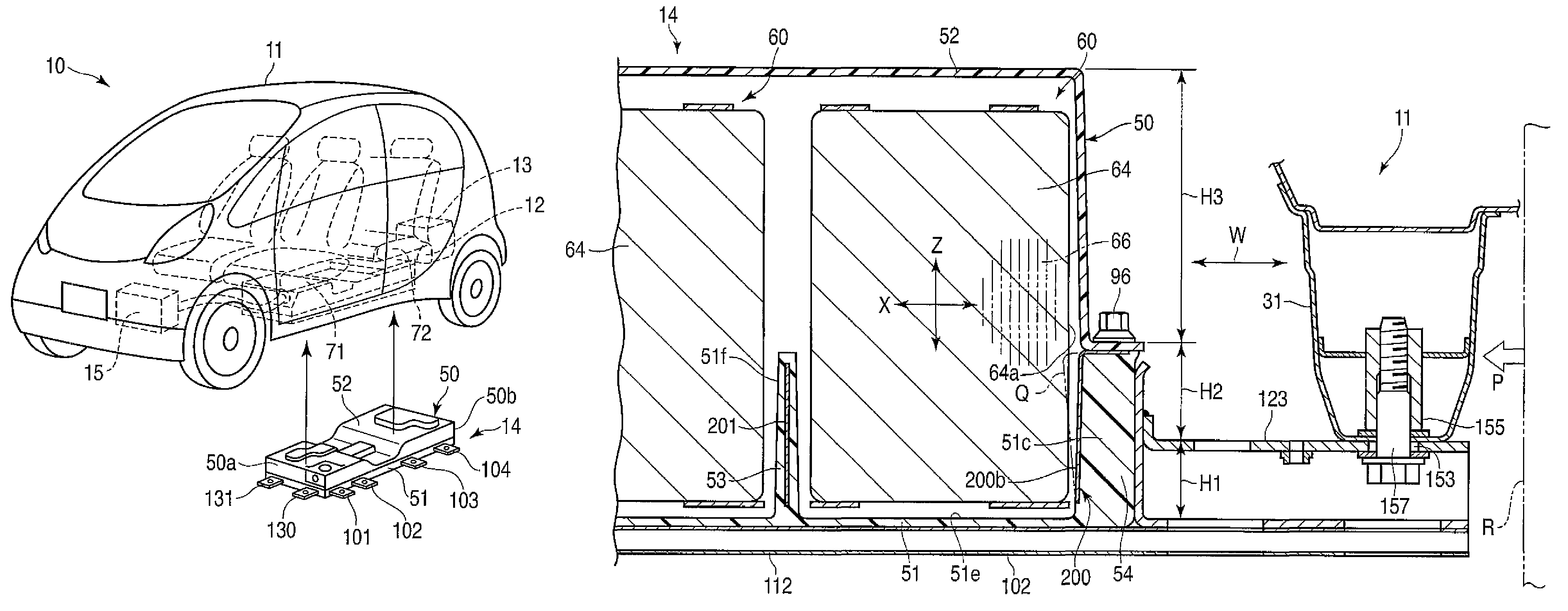
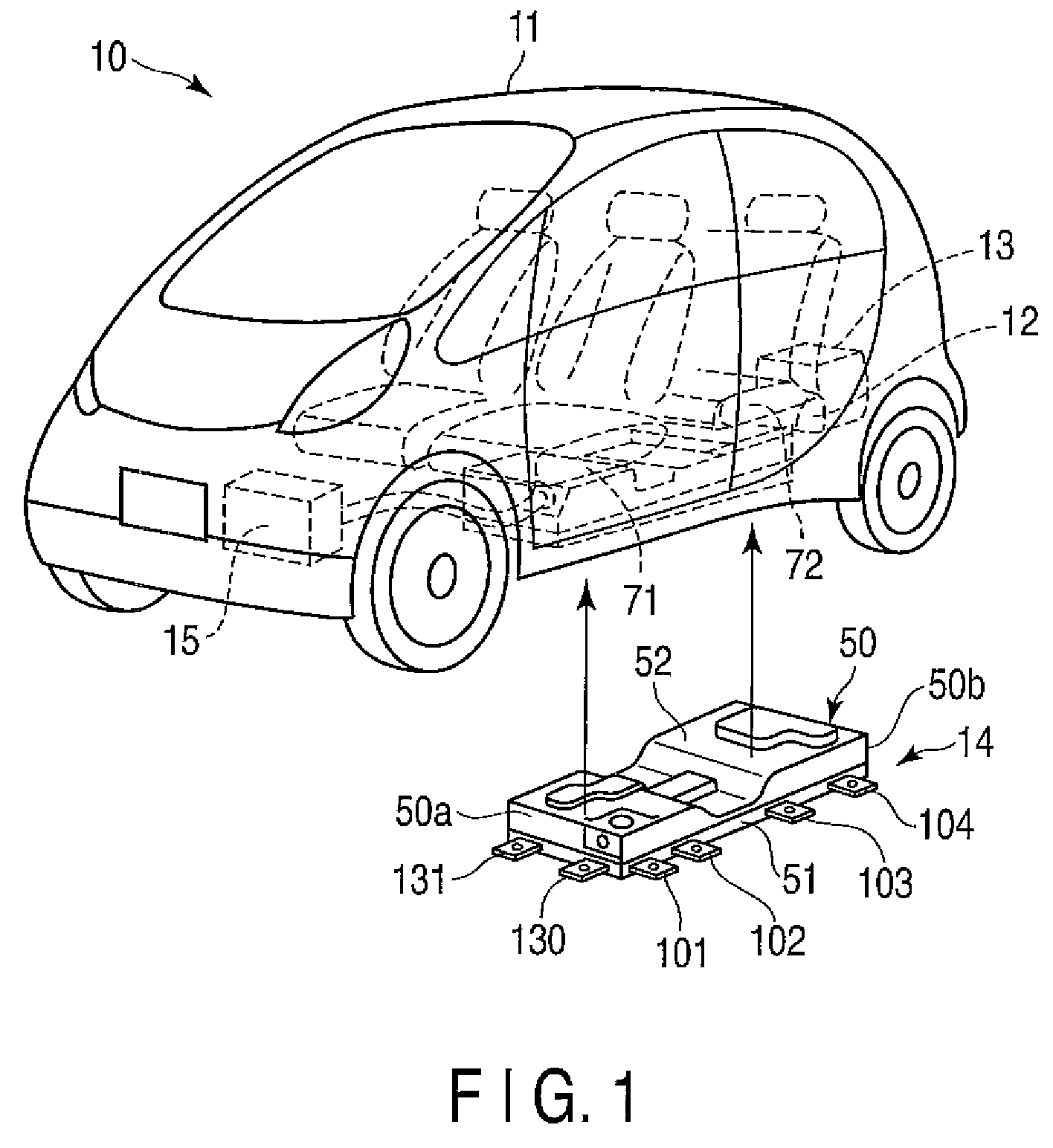
[0028]FIG. 1 shows an example of an electric vehicle 10. The electric vehicle 10 is provided with a traction motor 12 and a charger 13, which are located at the rear part of a vehicle body 11, a battery unit 14 under the floor of the vehicle body 11, etc. A heat exchange unit 15 for cooling and heating is disposed in the front part of the vehicle body 11.

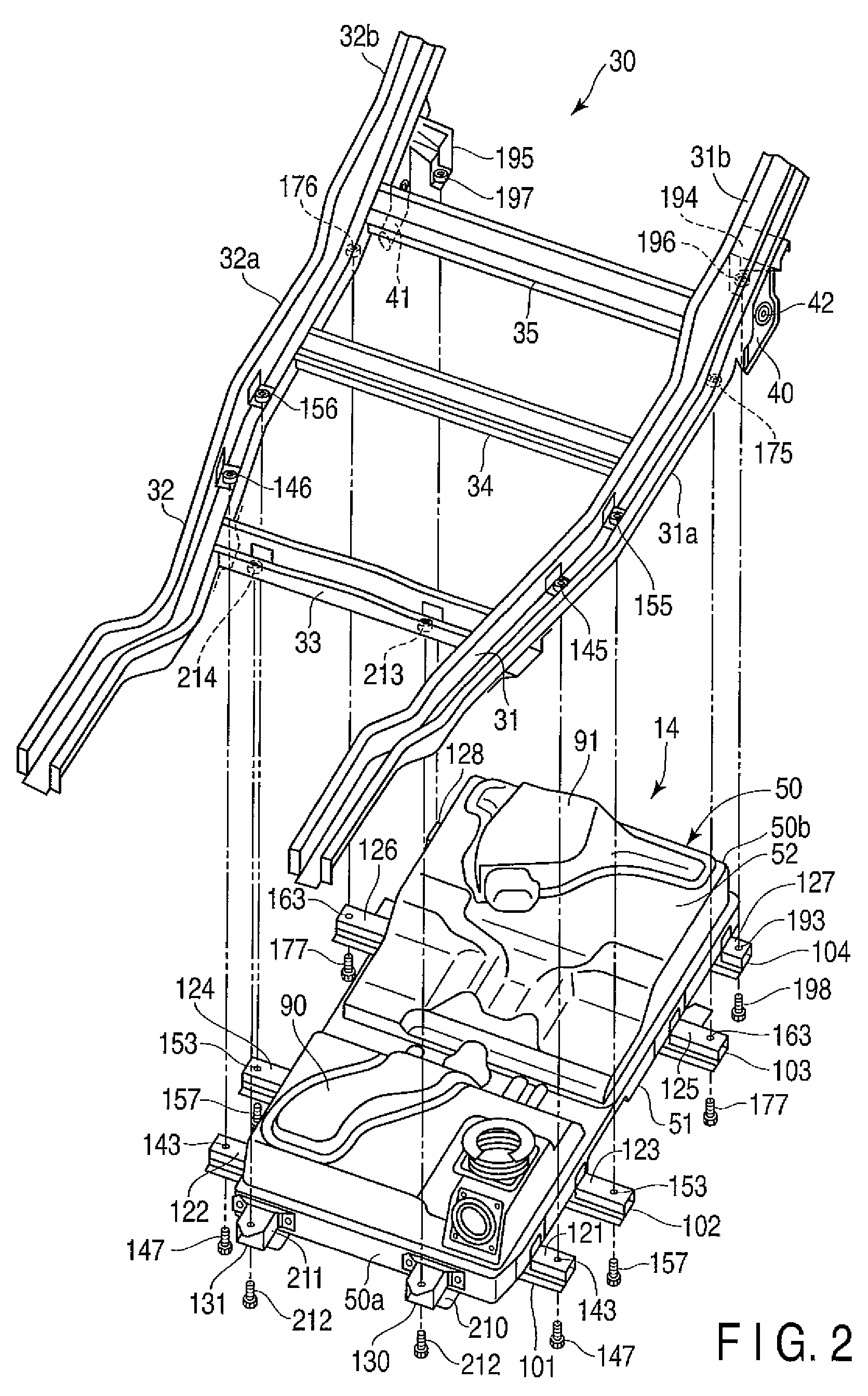
[0029]FIG. 2 shows a frame structure 30, which forms a framework of the lower part of the vehicle body 11, and the battery unit 14 to be mounted on the frame structure 30. The frame structure 30 includes a pair of side members 31 and 32 (left and right), which extend in the longitudinal direction of the vehicle body 11, and cross members 33, 34 and 35 extending in the width direction of the vehicle body 11. The cross members 33, 34 and 35 are fixed in predetermined positions on the side members 31 and 32 by welding.

[0030]Suspension ar...


PUM


Abstract

A battery unit mounted in an electric vehicle is provided with a battery case and a plurality of battery modules. The battery case includes a tray member on the lower side and a cover member on the upper side. The tray member is fixed to side members by a beam member extending in a width direction of a vehicle body. Each battery module is composed of a plurality of cells. Among all the cells contained in the battery case, at least those cells on the outer peripheral side which are located near a flank of the vehicle body are located on the tray member so that a lamination direction of cell elements is coincident with the width direction of the vehicle body.

Description

CROSS-REFERENCE TO RELATED APPLICATIONS[0001]This application is based upon and claims the benefit of priority from prior Japanese Patent Application No. 2007-314989, filed Dec. 5, 2007, the entire contents of which are incorporated herein by reference.BACKGROUND OF THE INVENTION[0002]1. Field of the Invention[0003]The present invention relates to an electric vehicle configured to be driven by a motor using a battery unit as a power source.[0004]2. Description of the Related Art[0005]A battery unit used in an electric vehicle includes a battery module composed of a plurality of cells, a battery case that contains the battery module, etc. The battery case is provided with, for example, a tray member that supports the battery module, a cover member that covers the top of the tray member, etc. Cells are secondary batteries, such as lithium-ion batteries.[0006]A structure has been made to reduce damage to a vehicle body and a battery unit in case of a collision of an electric vehicle th...

Claims


Application Information

Patent Timeline
Patent Type & Authority Patents(United States)
IPC IPC(8): B60R16/04B60K1/04B60L50/64
CPCB60K1/04H01M10/48H01M2/1077H01M2/1083B60K2001/0472H01M2/0217B60L50/66Y02T10/70Y02E60/10H01M50/103H01M50/249H01M50/278B60L50/64H01M50/227H01M50/211H01M50/244B62D21/15B60Y2306/01B60Y2200/91
Inventor TAKASAKI, SEIICHIISOGAI, TOSHIAKI
Owner MITSUBISHI MOTORS CORP
Why Eureka
Try Eureka