Single-pole electrical connector having a steel retaining spring

Active Publication Date: 2010-02-09
HUBBELL INC
View PDF26 Cites 21 Cited by
  • Summary
  • Abstract
  • Description
  • Claims
  • Application Information

AI Technical Summary

Benefits of technology

[0006]Accordingly, it is a primary objective of the present invention to provide a male contact of a male plug of a

Problems solved by technology

Inadequate spring force or yielding springs on the slotted male contact decreases the electrical transmitt

Method used


Image

  • Single-pole electrical connector having a steel retaining spring
  • Single-pole electrical connector having a steel retaining spring
  • Single-pole electrical connector having a steel retaining spring

Examples


Embodiment Construction

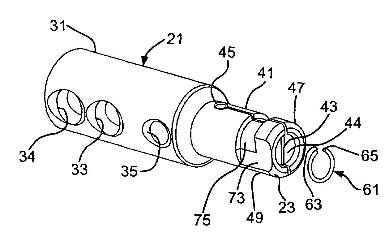
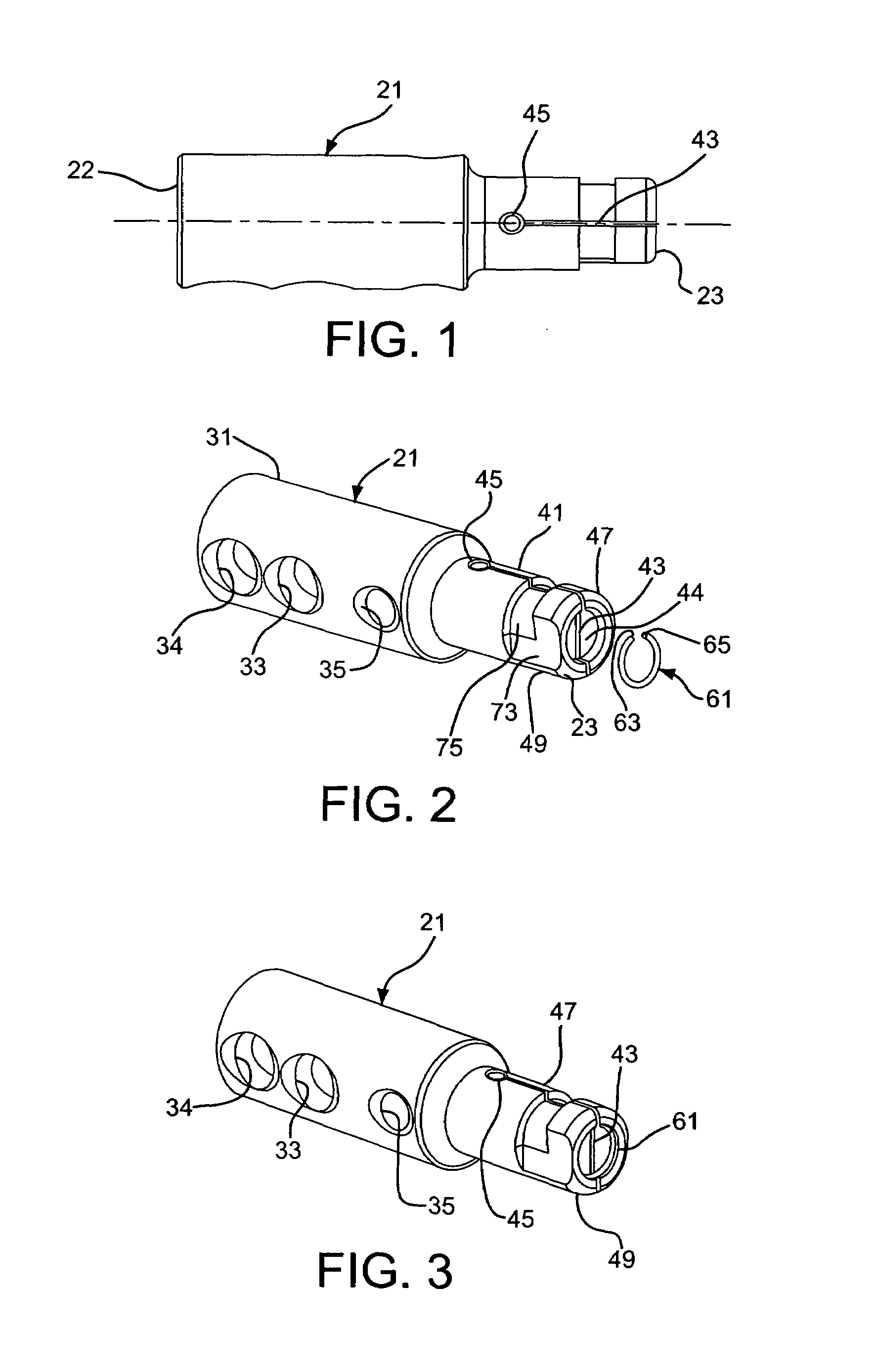
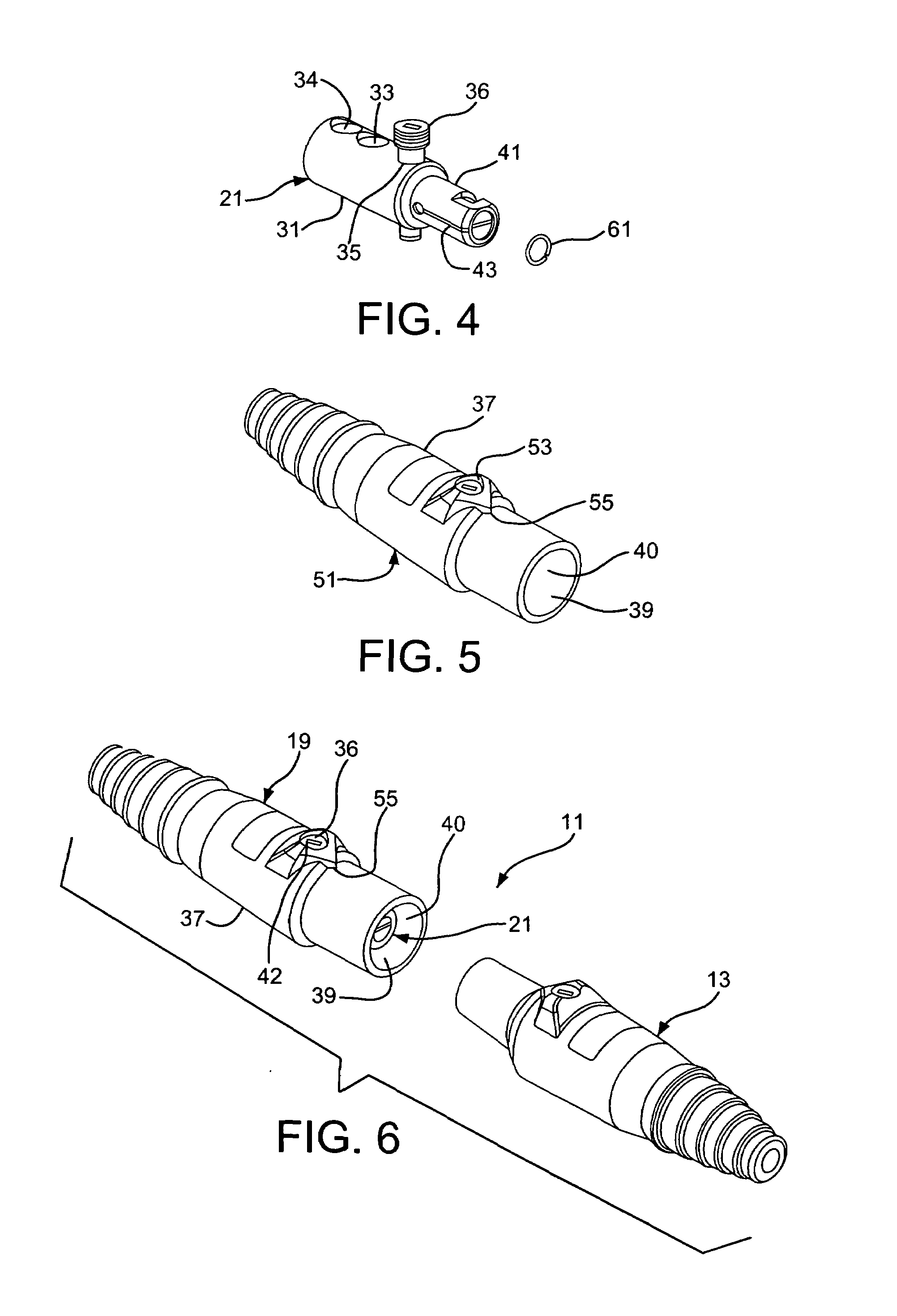
[0028]As shown in FIGS. 1-11, the present invention includes a single-pole electrical connector assembly 11. A retainer spring 61 substantially prevents slotted portions 47 and 49 of a male contact 21 of a male plug 19 from yielding or fatiguing, thereby facilitating the electrical transmission capabilities of the single-pole electrical connector assembly 11 as well as substantially preventing high thermal temperatures from occurring due to a poor connection between the male plug 19 and female contact 13 of the single-pole electrical connector assembly.

[0029]The single-pole electrical connector assembly 11, as shown in FIGS. 6 and 7, includes a male plug 19 and a female contact 13. Electrical cables 15 and 17 are connected to the male plug 19 and female contact 13, respectively. Connecting the male plug 19 and female contact 13, as shown in FIG. 7, enables the transmission of electrical power therethrough.

[0030]The male contact 21, as shown in FIGS. 1-4 and 8-11, has a first end 22 ...


PUM


Abstract

A male plug of a single-pole electrical connector assembly includes a non-conductive housing and a conductive contact having first and second ends disposed in the housing. The first end is adapted to receive an electrical cable and the second end is adapted to engage a corresponding female contact. An axially extending slot is formed in the contact and extends toward the first end of the contact from the second end. The slot forms first and second slotted portions of the contact. A spring disposed proximal the second end of the contact substantially prevents yielding of the first and second slotted portions of the contact and biases the first and second slotted portions radially outwardly.

Description

FIELD OF THE INVENTION[0001]The present invention relates to a male plug of a single-pole electrical connector. More particularly, the present invention relates to a spring connected to a slotted male plug of a single-pole electrical connector. Still more particularly, the present invention relates to a retainer spring disposed in an end of a slotted male plug of a single-pole electrical connector, thereby substantially preventing yielding of the slotted portions of the male plug.BACKGROUND OF THE INVENTION[0002]Single-pole electrical connectors are typically used for supplying temporary electrical power and are configured to connect and disconnect quickly and easily. The single-pole electrical connectors include a male plug having a pin and a female contact having a sleeve. The male plug and female contact are generally rated for 600 volts max and up to 400 amps max.[0003]The contact of the male plug and the sleeve of the female contact are high conductivity brass contacts that are...

Claims


Application Information

Patent Timeline
IPC IPC(8): H01R11/22
CPCH01R13/426H01R13/17H01R4/36H01R2101/00
Inventor SCANZILLO, THOMAS L.BRACCI, THOMAS W.
Owner HUBBELL INC
Why Eureka
Try Eureka