Flush toilet

a toilet and flushing technology, applied in water closets, water installations, constructions, etc., can solve the problems of affecting the cleaning effect of the toilet, the adherence of dirty materials, and the region between the rim and the underside of the toilet, so as to achieve efficient bowl cleaning and waste discharge

Active Publication Date: 2010-02-16
TOTO LTD
View PDF9 Cites 49 Cited by
  • Summary
  • Abstract
  • Description
  • Claims
  • Application Information

AI Technical Summary

Benefits of technology

[0014]It is therefore an object of the present invention to provide a flush toilet that by producing a vortex of cleansing water that extends thoroughly to reach the extremities can achieve efficient bowl cleansing and waste discharge, irrespective of whether utilizing a tank or connected directly to a service water pipe.
[0015]Another object of the present invention is to provide a flush toilet that is excellent in both cleansing performance and waste discharge performance even when equipped with a water-conserving tank.

Problems solved by technology

However, this type of flush toilet has a problem in that the boundary region between the rim undersurface and the waste receiving surface is a blind area that cannot be seen from above.
Dirty matter is therefore liable to remain at this region, particularly on the rim undersurface, which is not reached by the cleansing water vortex.
This also leads to adherence of dirty matter.
Consideration is also given to the fact that causing the cleansing water to complete a full circle is not practical because the long distance involved would necessitate a high water discharge pressure.
In addition, the need to spread the cleansing water uniformly throughout would restrict freedom of shape selection.
A flush toilet using a cleansing water tank unavoidably experiences a decline in waterhead during supply of cleansing water from the tank to the toilet because the amount of water in the tank decreases as flushing proceeds.
When an attempt is made to secure a vortex sufficient for cleansing by increasing the waterhead, the amount of water discharged from the individual water spouts at the start of flushing increases to the point that the cleansing water is liable to spew out of the bowl.
Moreover, cleansing of the bowl is liable to be inadequate because at the final stage of flushing the cleansing water vortex does not reach the extremities sufficiently.
When the pressure of the service water supplied to the water spout(s) is low, however, the cleansing water vortex becomes insufficient to make thorough flushing of the toilet impossible.
No. 1 and Ref No. 2 of using a distributor or the like to spout water in opposite lateral directions is disadvantageous in the point that the two oppositely directed vortices collide at the center region of the toilet bowl to cause splashing and also in the point that a smooth siphon effect is inhibited.
Although Ref No. 3 teaches a structure that uses multiple water spouts to form a vortex in a single direction, mere provision of multiple water spouts does not enable the flushing that the bowl (bowl surface) of a flush toilet requires to convey and discharge waste efficiently.
Namely, it involves problems from the practical aspect in that it makes no suggestion whatsoever regarding specific structural features for achieving these requirements, such as the location of the water spouts and method of supplying cleansing water to the water spouts.
In the case of the siphon jet flush toilet, however, a larger amount of water has to be supplied to the jet holes than to the water spouts that form the vortex.
As a result, cleansing of the bowl (surface) becomes insufficient because not enough water is supplied to the water spouts, thus posing a fundamental problem.

Method used


Image

  • Flush toilet
  • Flush toilet
  • Flush toilet

Examples


first embodiment

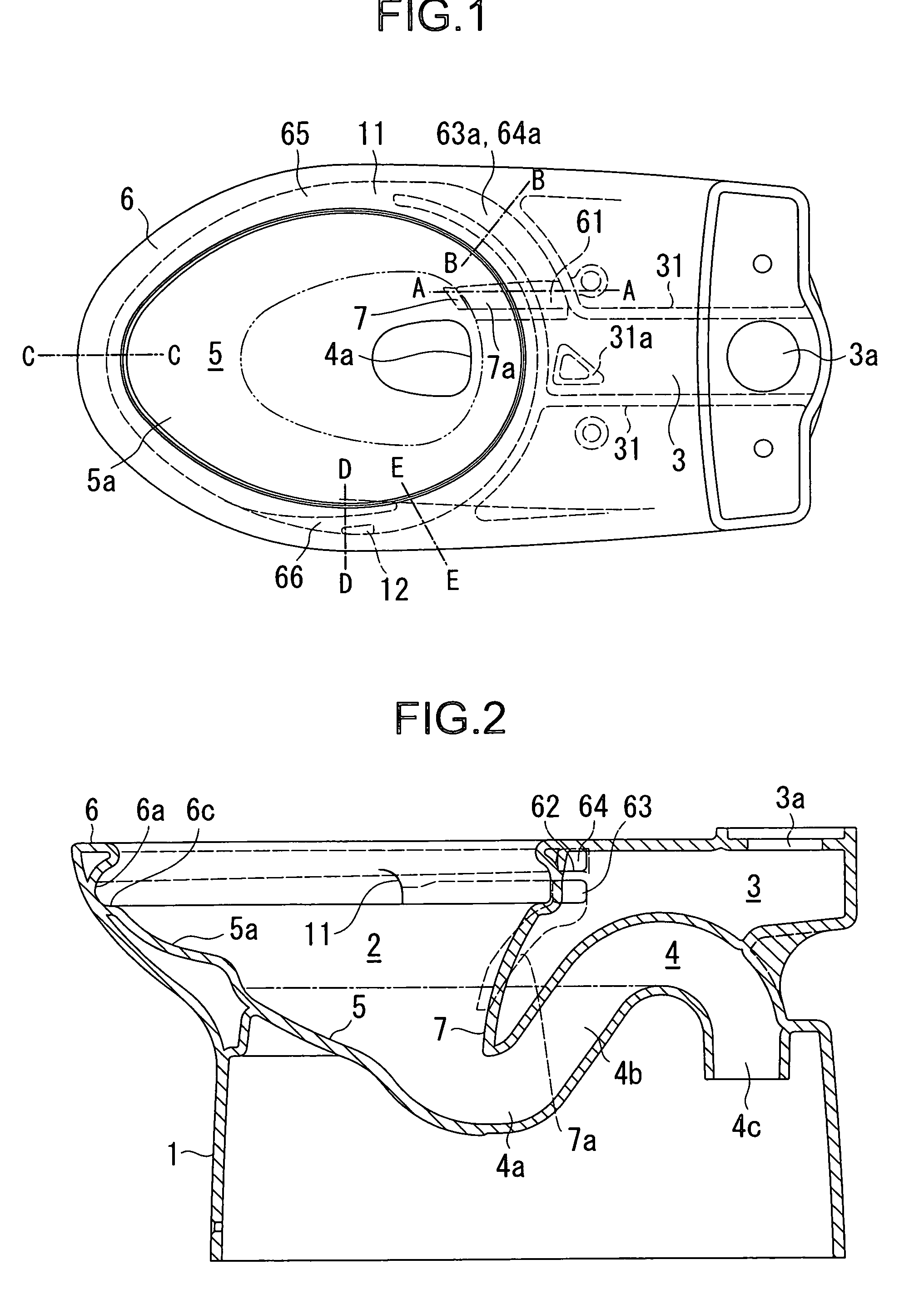
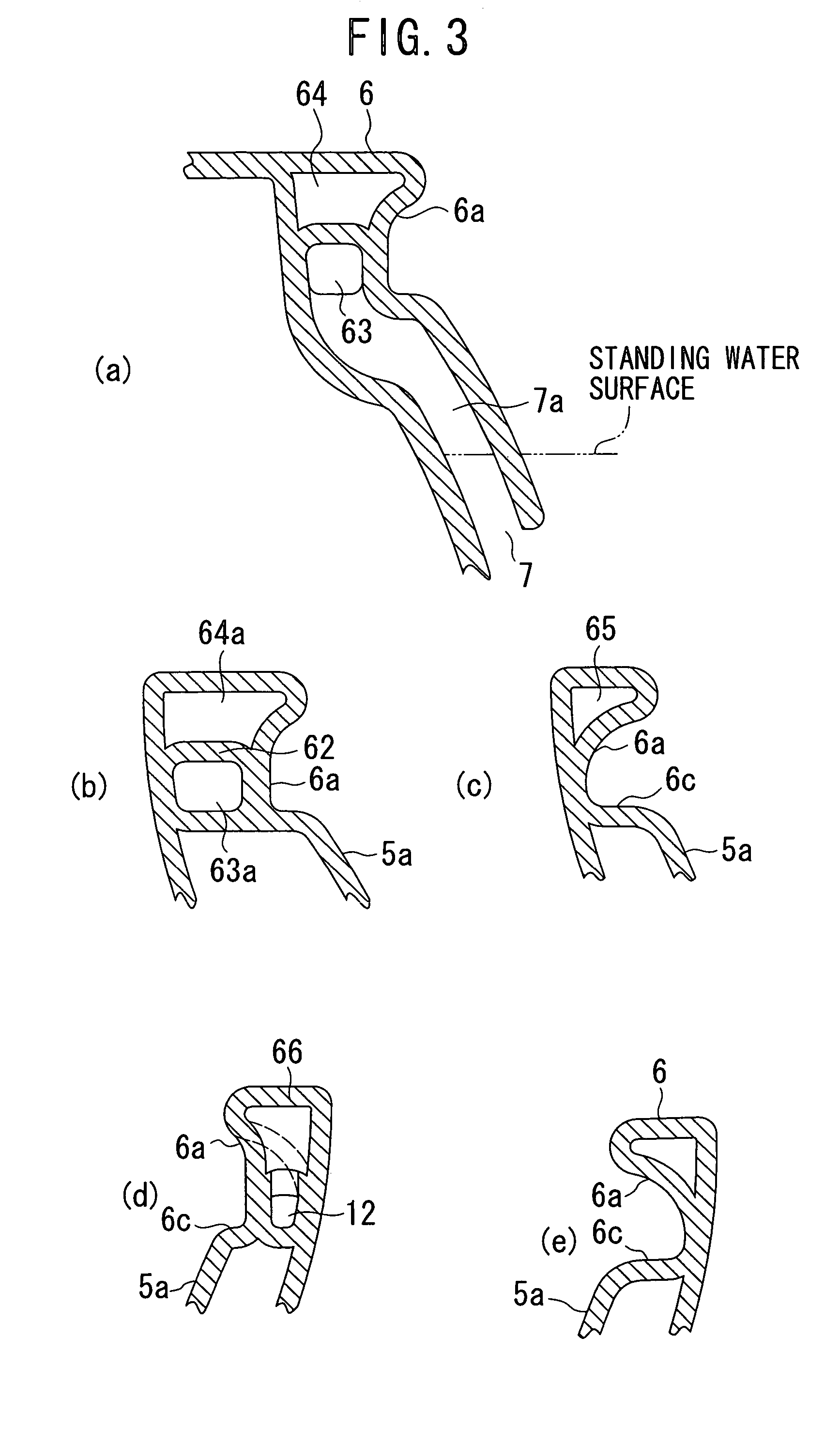
[0089]In the flush toilet according to this first embodiment, the flow of cleansing water supplied from a water source is divided into two streams by the rim communicating holes 63, 64. Cleansing water flowing in through the rim communicating hole 63 on the one hand passes through the floor opening 61 to be discharged from the force-flush cleansing water spout 7 toward the bowl bottom surface in the vicinity of the inlet 4a and on the other hand passes through the water channel 63a to be discharged from the first water spout 11. Cleansing water flowing in through the rim communicating hole 64 passes through the water channels 64a, 65, 66 to be discharged from the second water spout 12. The cleansing water discharged from the first and second water spouts 11, 12 produces a single vortex that reaches all portions of the waste receiving surface 5.

[0090]Next, a second embodiment of the present invention will be explained with reference to FIGS. 4 to 6. FIG. 4 is plan view showing a flus...

second embodiment

[0091]In the flush toilet the force-flush cleansing water spout 7 opens above the surface of the standing water and is adapted to spout cleansing water in the direction of force-flushing waste, particularly waste floating on the standing water surface, into the drainage channel 4.

[0092]The water channels 7a, 63a, 64a and the first and second water spouts 11, 12 are structured like those in the first embodiment.

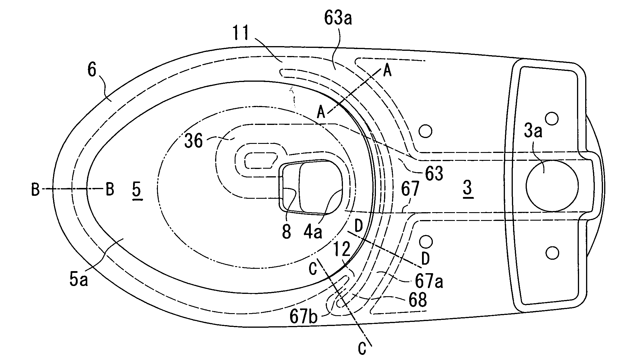
[0093]Next, a third embodiment of the present invention will be explained with reference to FIGS. 7 to 9. FIG. 7 is plan view showing a flush toilet that is a third embodiment of the present invention, FIG. 8 is a vertical sectional view of the flush toilet shown in FIG. 7, and FIG. 9 is a set of drawings in which (a) to (d) are partial sectional views taken along lines A-A to D-D in FIG. 7. Portions of the third embodiment like those of the first embodiment are assigned the same symbols as their counterparts in the first embodiment and will not be explained again.

third embodiment

[0094]The flush toilet is provided at a location opposite the inlet 4a with a jet hole 8 for efficiently force-flushing waste into the drainage channel 4.

[0095]Moreover, in the third embodiment, the water conduit 3 is divided by a partition 34 into an upper water conduit 30a and a lower water conduit 30b and cleansing water from the water source is supplied into the lower water conduit 30b through an opening 35 formed in the partition 34. The partition 34 prevents delay of siphoning occurrence owing to entrainment of air present in the water conduit into the cleansing water. The upper water conduit 30a communicates with the water channel 64a for supplying cleansing water to the second water spout 12 and the lower water conduit 30b communicates with the water channel 63a for supplying cleansing water to the first water spout 11 and with a water channel 36 for supplying cleansing water to the jet hole 8. The cleansing water supplied into the lower water conduit 30b passes through the...


PUM


Abstract

A flush toilet that uses a prescribed amount of cleansing water stored in a cleansing water tank to cleanse the toilet and discharge waste is disclosed. The flush toilet includes a bowl having a waste receiving surface, an overhanging rim and a shelf, a drainage channel whose inlet is connected to the bottom of the bowl for discharging waste, a first water spouting section for spouting cleansing water onto the shelf of the bowl to form a vortex; a second water spouting section for spouting cleansing water onto shelf of the bowl in the same direction as the swirling direction of the vortex, a first water channel for supplying cleansing water from the cleansing water tank to the first water spouting section, and a second water channel for supplying cleansing water from the cleansing water tank to the second water spouting section.

Description

TECHNICAL FIELD[0001]The present invention relates to a flush toilet, particularly to a flush toilet that produces a vortex to perform cleansing and discharge of waste.BACKGROUND ART[0002]The ordinary conventional flush toilet has a rim of rectangular cross-section formed at the upper edge portion. The interior of the rim is used as a water channel and the undersurface of the rim is formed with holes or slits for discharging cleansing water onto the waste receiving surface.[0003]However, this type of flush toilet has a problem in that the boundary region between the rim undersurface and the waste receiving surface is a blind area that cannot be seen from above. Dirty matter is therefore liable to remain at this region, particularly on the rim undersurface, which is not reached by the cleansing water vortex. Moreover, the boundary region sometimes cannot be thoroughly glazed owing to its concealed location. This also leads to adherence of dirty matter.[0004]In order to overcome this ...

Claims


Application Information

Patent Timeline
Patent Type & Authority Patents(United States)
IPC IPC(8): E03D11/00E03D11/08
CPCE03D11/08E03D2201/30E03D11/02
Inventor NAKAMURA, KENICHIOZEKI, TSUYOSHIYONEDA, TOSHIFUMIICHIKI, TOMOYASUTOMONARI, HIROSHIASADA, KYOJIKAWAKAMI, KATSUHIRO
Owner TOTO LTD
Why Eureka
Try Eureka