Magnetic resonance imaging apparatus with a movable RF coil having a controllable distance between the movable RF coil and an imaged body surface

a magnetic resonance imaging and controllable distance technology, applied in the field of magnetic resonance imaging apparatus, can solve the problems of difficult to obtain a tomographic image with high sensitivity, impose a burden on an object and an operator, and difficult to obtain a tomographic image with more even sensitivity, etc., and achieve the effect of satisfying quality

Inactive Publication Date: 2010-02-16
TOSHIBA MEDICAL SYST CORP
View PDF13 Cites 22 Cited by
  • Summary
  • Abstract
  • Description
  • Claims
  • Application Information

AI Technical Summary

Benefits of technology

[0026]The magnetic resonance imaging apparatus and the magnetic resonance imaging method as described above make it possible to allow an image with more satisfactory quality to be obtained by adjusting a distance between a local radio frequency coil for receiving the nuclear magnetic resonance signal and a body surface of the object so as to be a more appropriate distance.

Problems solved by technology

However it is difficult to obtain a tomographic image with high sensitivity since the distance from a body surface of an object is farther than that in a case where a local RF coil is used.
Therefore, it is necessary to take out an object from the bed and reset local RF coils on each change of imaged body part, thereby imposing a burden on an object and an operator.
Hence, the sensitivity of the local RF coil unit 3 becomes uneven, thereby being difficult to obtain a tomographic image with more even sensitivity.
This situation leads to reduced quality of a tomographic image.

Method used


Image

  • Magnetic resonance imaging apparatus with a movable RF coil having a controllable distance between the movable RF coil and an imaged body surface
  • Magnetic resonance imaging apparatus with a movable RF coil having a controllable distance between the movable RF coil and an imaged body surface
  • Magnetic resonance imaging apparatus with a movable RF coil having a controllable distance between the movable RF coil and an imaged body surface

Examples


first embodiment

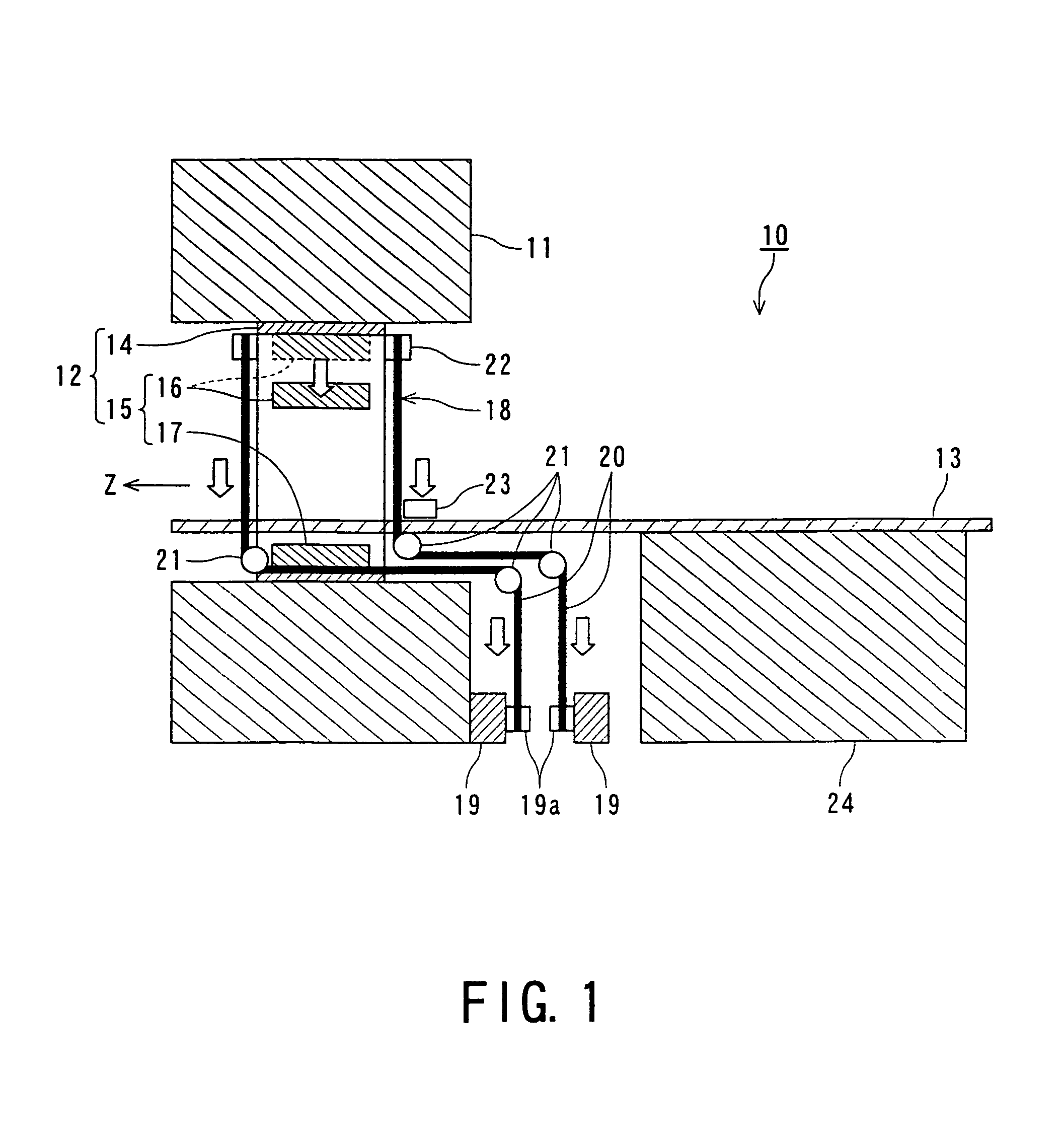
[0038]FIG. 1 is a diagram showing a magnetic resonance imaging apparatus according to the present invention.

[0039]A magnetic resonance imaging apparatus 10 includes a magnet 11 and a RF coil unit 12. The magnet 11 housing gradient coils (not shown) is used for forming a static magnetic field. The magnet 11 is formed cylindrically. An imaging area is set in the inside of the magnet 11. The RF coil unit 12 and a bed 13 for setting an object are also arranged in the inside of the magnet 11.

[0040]The RF coil unit 12 has a WB coil 14 and a local RF coil set 15. The WB coil 14 may not be provided. The WB coil 14 images a large area of an about 50 cm view for example. The local RF coil set 15 including a coil for use on a head, a genicula and a spine images a specific part including a head, a genicula and a spine.

[0041]The WB coil 14 is formed cylindrically. An arbitrary number of the local RF coils 15 each having a predetermined shape are arranged at arbitrary positions in the inside of t...

second embodiment

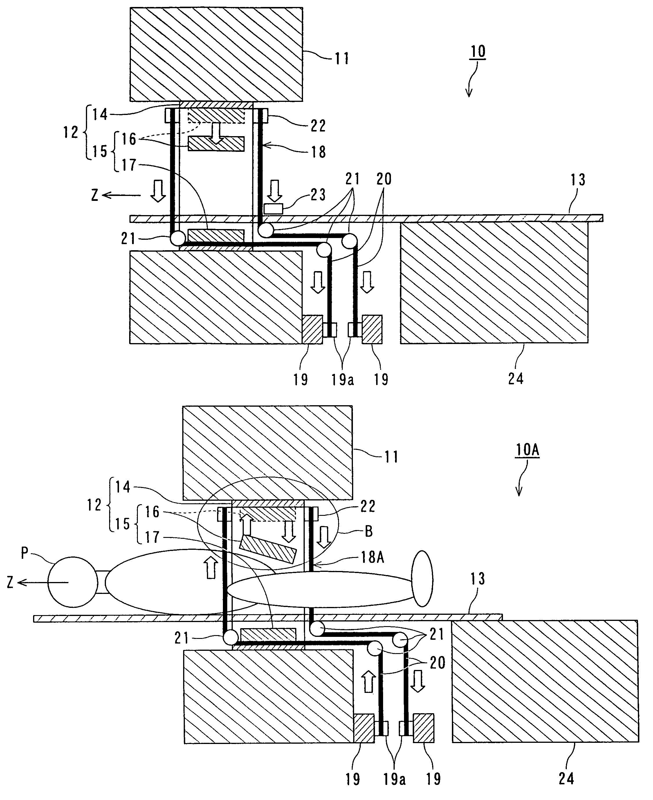
[0065]FIG. 5 is a diagram showing a magnetic resonance imaging apparatus according to the present invention.

[0066]In the magnetic resonance imaging apparatus 10A shown in FIG. 5, a structure and function of the RF coil drive structure 18A are different from those of the magnetic resonance imaging apparatus 10 shown in FIG. 1. Other constructions and operations of the magnetic resonance imaging apparatus 10A are not substantially different from those of the magnetic resonance imaging apparatus 10 shown in FIG. l. Therefore, the same reference numbers are used to identify the same elements as those of the magnetic resonance imaging apparatus 10 without again explaining their respective structures and functions.

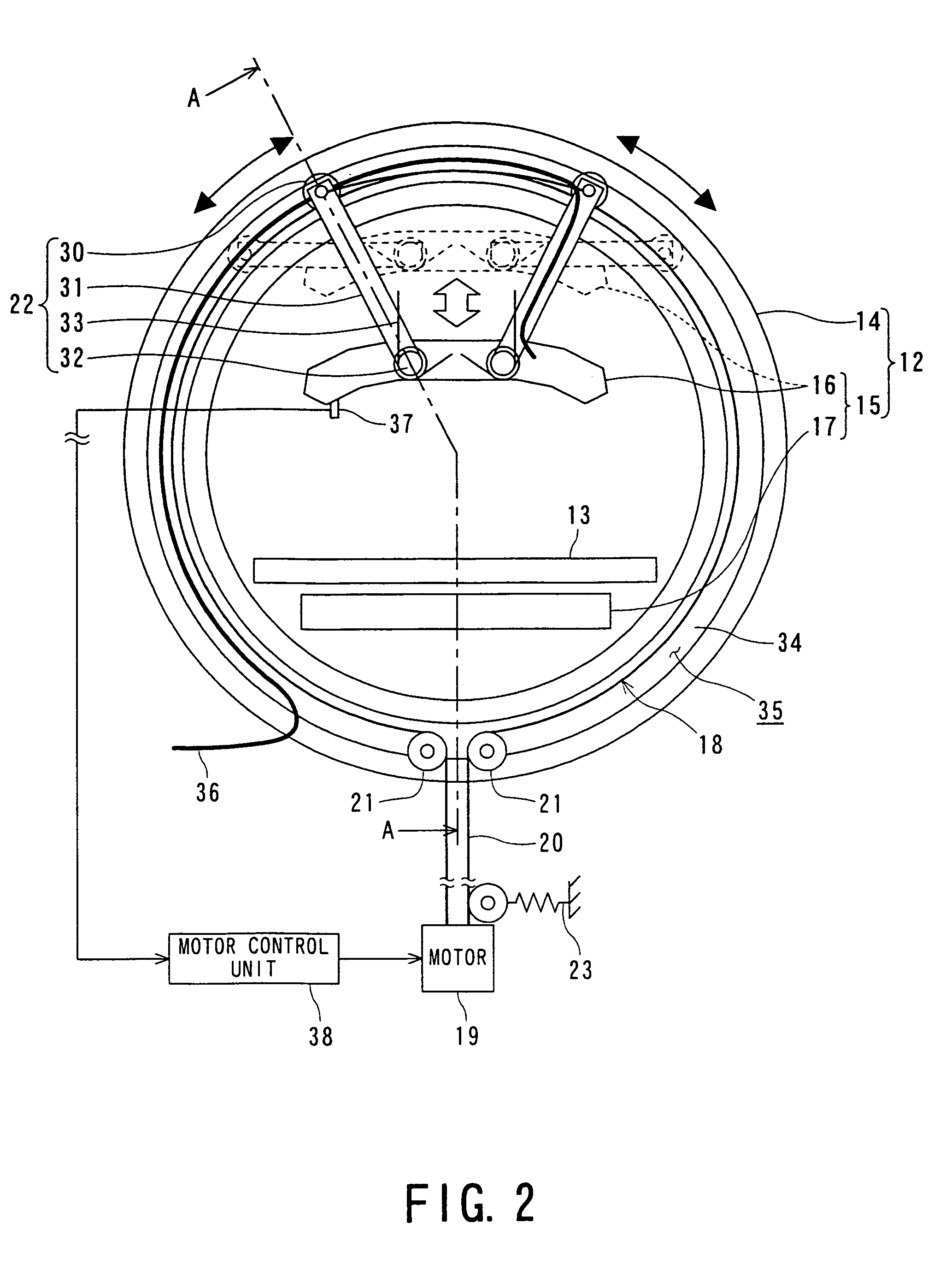
[0067]The RF coil drive structure 18A of the magnetic resonance imaging apparatus 10A has an arbitrary structure. For example, the RF coil drive structure 18A includes motors 19, nonconductive wires 20, pulleys 21 and a power transmission structure 22. Then, power from motors 19...

third embodiment

[0075]FIG. 8 is a diagram showing a magnetic resonance imaging apparatus according to the present invention.

[0076]In the magnetic resonance imaging apparatus 10B shown in FIG. 8, a structure and function of the RF coil drive structure 18B are different from those of the magnetic resonance imaging apparatus 10 shown in FIG. 1. Other constructions and operations of the magnetic resonance imaging apparatus 10B are not substantially different from those of the magnetic resonance imaging apparatus 10 shown in FIG. 1. Therefore, the same reference numbers are used to identify the same corresponding elements as found in magnetic resonance imaging apparatus 10 without repeating explanation thereof.

[0077]The RF coil drive structure 18B of the magnetic resonance imaging apparatus 10B has a function to park the movable RF coil 16. That is, the RF coil drive structure 18B also functions as a parking structure. The RF coil drive structure 18B has coil side rollers 50 corresponding to the wires 2...


PUM


Abstract

A magnetic resonance imaging apparatus comprising: a magnet configured to form a static magnetic field in an imaging area; a cylindrical structure having a guide; a radio frequency coil configured to receive a nuclear magnetic resonance signal generated by transmitting a radio frequency signal into a object set in the static magnetic field; and a radio frequency coil drive structure configured to adjust a distance between the radio frequency coil and a body surface of the object by using a moving structure configured to move along with the guide, a wire configured to move the moving structure and a motor connected to the wire.

Description

BACKGROUND OF THE INVENTION[0001]1. Field of the Invention[0002]The present invention relates to a magnetic resonance imaging apparatus and a magnetic resonance imaging method which reconstruct an image using a NMR (nuclear magnetic resonance) signal generated by transmitting a RF (radio frequency) signal with a Larmor frequency into an object and forming a gradient magnetic field inside a magnet for a static magnetic field by a gradient coil, and more particularly, to a magnetic resonance imaging apparatus and a magnetic resonance imaging method which allow an image with more satisfactory quality to be obtained by adjusting a distance between a radio frequency coil for receiving the nuclear magnetic resonance signal and a body surface of the object.[0003]2. Description of the Related Art[0004]Conventionally, a magnetic resonance imaging (MRI) apparatus is used as a monitoring apparatus in the medical field.[0005]The magnetic resonance imaging apparatus is an apparatus which reconst...

Claims


Application Information

Patent Timeline
Patent Type & Authority Patents(United States)
IPC IPC(8): G01V3/00
CPCG01R33/28G01R33/34007
Inventor TAKAMORI, HIROMITSU
Owner TOSHIBA MEDICAL SYST CORP
Why Eureka
Try Eureka