Metal display panel having one or more translucent regions

a technology of metal display panel and translucent region, which is applied in the direction of identification means, instruments, manufacturing tools, etc., can solve the problems of difference in materials, inability to fully integrate the display unit in the front of the device, and display suffers, so as to avoid stains and marks, the effect of pleasing surface characteristics and appearan

Active Publication Date: 2010-02-16
KONINKLIJKE PHILIPS ELECTRONICS NV +1
View PDF14 Cites 75 Cited by
  • Summary
  • Abstract
  • Description
  • Claims
  • Application Information

AI Technical Summary

Benefits of technology

[0025]In a still further advantageous embodiment the means for detecting input are not touch-sensitive, such as for example optical means. This embodiment is especially advantageous in use where the surfaces for the display and input unit is part of the surface for an electronic device such as for example a radio, hi-fi, television, oven, cooker, refrigerator and the like, where it is desirable to provide the user with an aesthetically pleasing surface, for example in the form of a brushed aluminium or brushed stainless steel surface. In order to avoid the stains and marks from touching the surface which necessitate cleaning in order to achieve the pleasing surface characteristics and appearance again, the optical means does not require the user to actually touch the unit in order to provide the desired input.

Problems solved by technology

However, often such displays suffer from a number of disadvantages.
However, the display region will still be visible to a viewer also in the deactivated state since most often the display will be made of a front material different from the front material of the device to which the display is attached, because often a front panel of a device is a metal panel, thus making it impossible to fully integrate the display unit in the front of the device.
If a display panel is attached to a device having a metal front panel the difference in materials will also imply a non-perfect mechanical fit of the display onto or into the front panel of the device.
This non-perfect mechanical fit will lead to further disadvantages than non-perfect visual fit as mentioned above.
In addition, attaching a display panel to a front panel of a device will normally involve a penetration of the front panel, such as for electrical wires, thus introducing a path for dust, liquid and gases that may penetrate into the interior of the device thus disturbing the function of the device.
The document, however, does not describe that the structure may also be used as an input unit, whereby it leaves the serious drawback that for applications, where it is desirable both to display information, but also to receive input, the skilled person will have to provide separate input means, for example in the shape of traditional bottoms, dials, etc.
However, as an example, a glass material must still be used for supporting the metal layer and thereby the visual appearance of an integrated display region and front panel is destroyed.
However, the object includes that when the light source is switched off, the display region should not in any way be distinguishable from the remaining part of the panel.

Method used


Image

  • Metal display panel having one or more translucent regions
  • Metal display panel having one or more translucent regions
  • Metal display panel having one or more translucent regions

Examples


Embodiment Construction

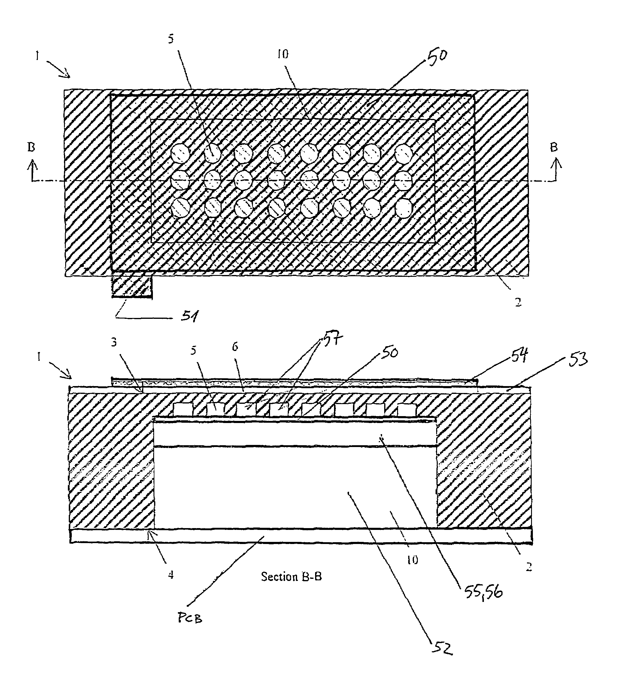
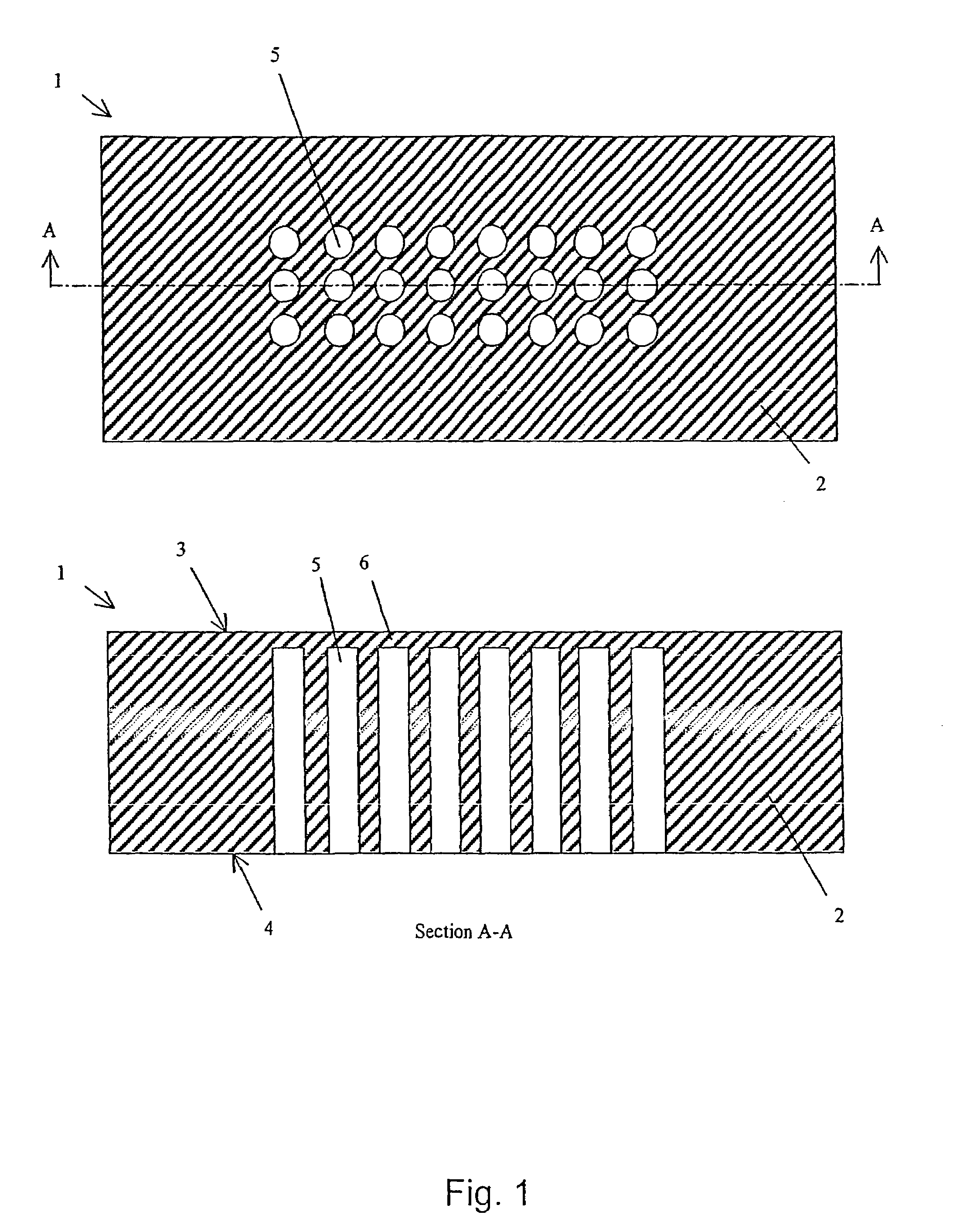
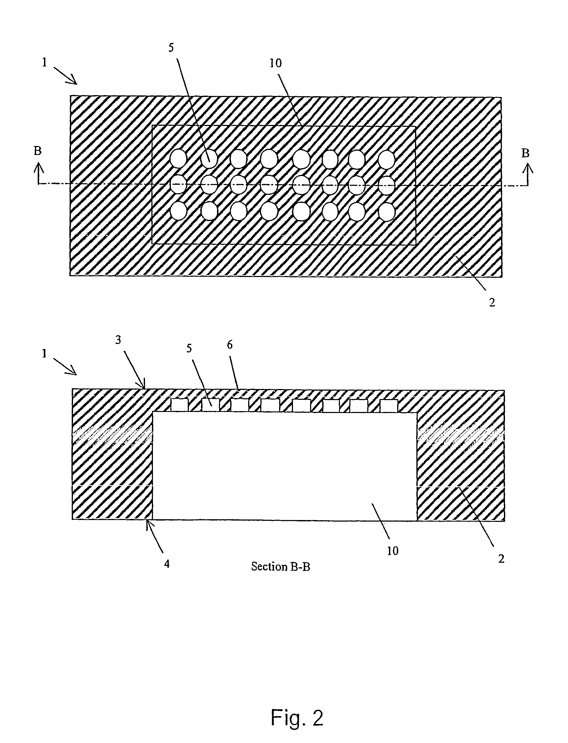
[0041]The technical effect of the invention is that the metal structure can be used for display of information when viewed from a front side of the metal structure. A display region has shapes so as to form symbols intended for providing a viewer with information when a light source is switched on at a rear side of the metal structure. With the light source switched off, the front side of the metal structure has the appearance of a solid metallic surface—both with respect to visual and touchable appearance and with respect to structural appearance. In the mode where the light is switched off, the appearance is such that no indication is given to a potential user that the input display unit is different from any other metal structure made from the same material. As example, the metal structure may be a plate, a sheet or a foil of aluminium, magnesium, titanium, zinc, brass, stainless steel alloys, copper or the like. Chemically plated metallic surfaces on a metal basement such as chr...


PUM

PropertyMeasurementUnit
pore diameteraaaaaaaaaa
diameteraaaaaaaaaa
thicknessaaaaaaaaaa

Abstract

A metal structure (1) has a display region being a second region and being integrate with another region being a first region which is a display region. The metal structure may constitute a monolithic structure of an information display unit, for example, a front panel of an electronic device. The display region is formed by providing a cluster of small non-through-going cavities (5) in the metal structure, leaving a very small thickness of material, the thickness being translucent (6). In addition to being a display unit when arranging a light source behind the translucent region (6), touch sensitive or non-touch sensitive input devices, optionally connected to acoustical input and registration devices, may also be provided. These input devices may advantageously be arranged in, or adjacent, the cavities in the metal structure, whereby when the front of the metal structure is viewed an indication of display or input options is visible.

Description

[0001]This application claims the benefit of PCT Application No. PCT / DK03 / 00126 filed Feb. 27, 2003 and PCT / DK2004 / 000113 filed 20 Feb. 2004, which are hereby incorporated by reference in their entirety.FIELD OF THE INVENTION[0002]The invention relates to a metal structure with one or more translucent regions. The translucent regions may form symbols and thus the metal structure may serve as an information display or input device. Accordingly, the invention also relates to an information display unit and / or input device and / or a combined information display unit and input device incorporating such a metal structure.BACKGROUND OF THE INVENTION[0003]Display units for providing visual information by applying light from a rear side of a transparent panel with pre-formed symbols are well-known. However, often such displays suffer from a number of disadvantages. It is normally a prerequisite desire of the transparent panels that the information symbols are completely invisible in a deacti...

Claims


Application Information

Patent Timeline
Patent Type & Authority Patents(United States)
IPC IPC(8): G06F3/042G09F9/305G09F13/04G09F13/06G09F13/08G09F27/00
CPCG09F9/305G09F13/04G09F13/06B23K26/4095G09F27/00B23K26/385B23K26/402G09F13/08B23K26/40B23K26/389B23K2101/35B23K2103/50
Inventor BLADT, HENRIK HENRIKSEN
Owner KONINKLIJKE PHILIPS ELECTRONICS NV
Why Eureka
Try Eureka