Driving mechanism, driving device, and lens driving device
a driving mechanism and lens technology, applied in the direction of instruments, printers, cameras, etc., can solve the problems of difficult to reduce the size and weight of the lens driving device, and achieve the effect of great and stably moving the driven member and reducing the size and weight thereo
- Summary
- Abstract
- Description
- Claims
- Application Information
AI Technical Summary
Benefits of technology
Problems solved by technology
Method used
Image
Examples
first embodiment
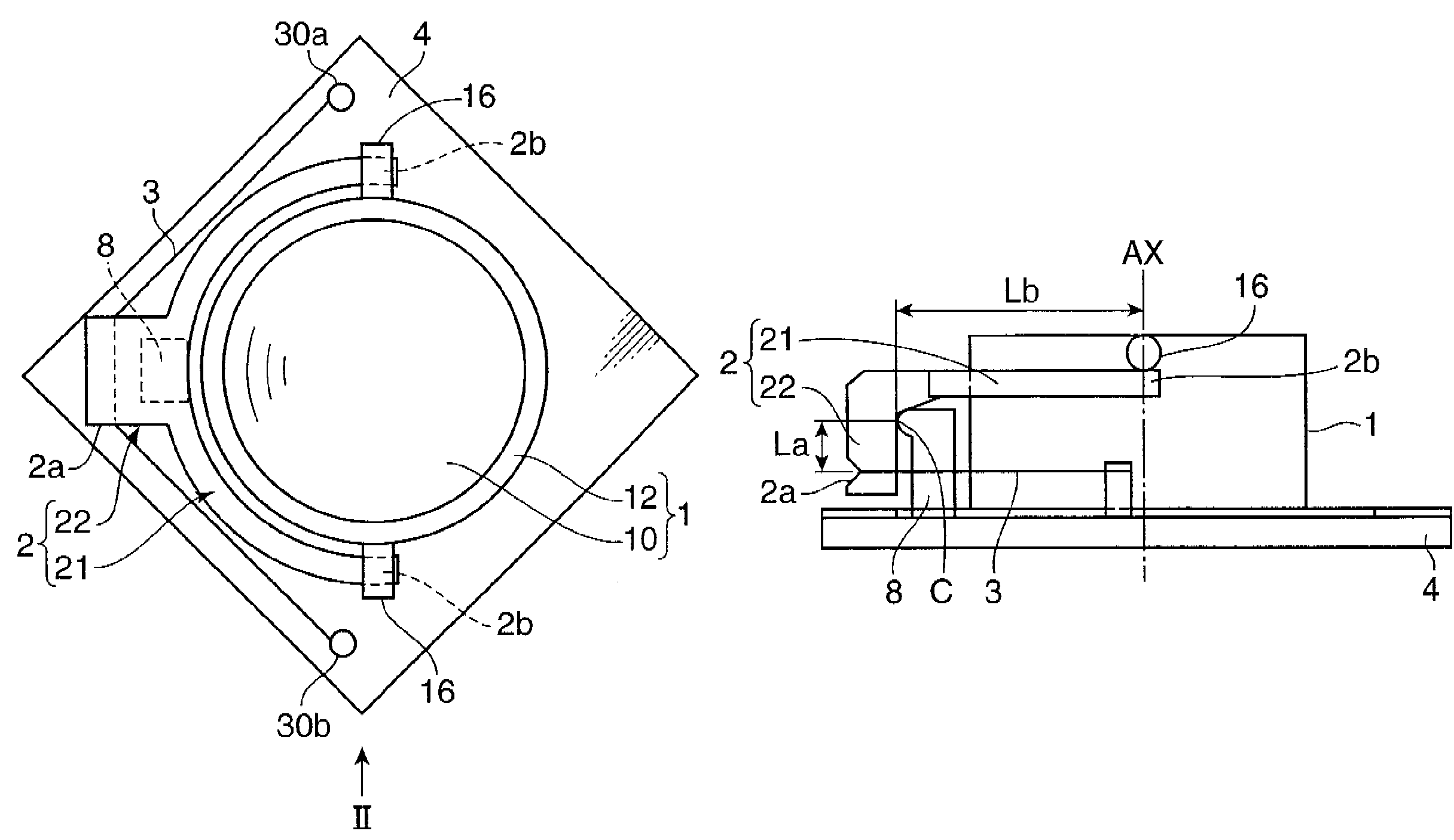
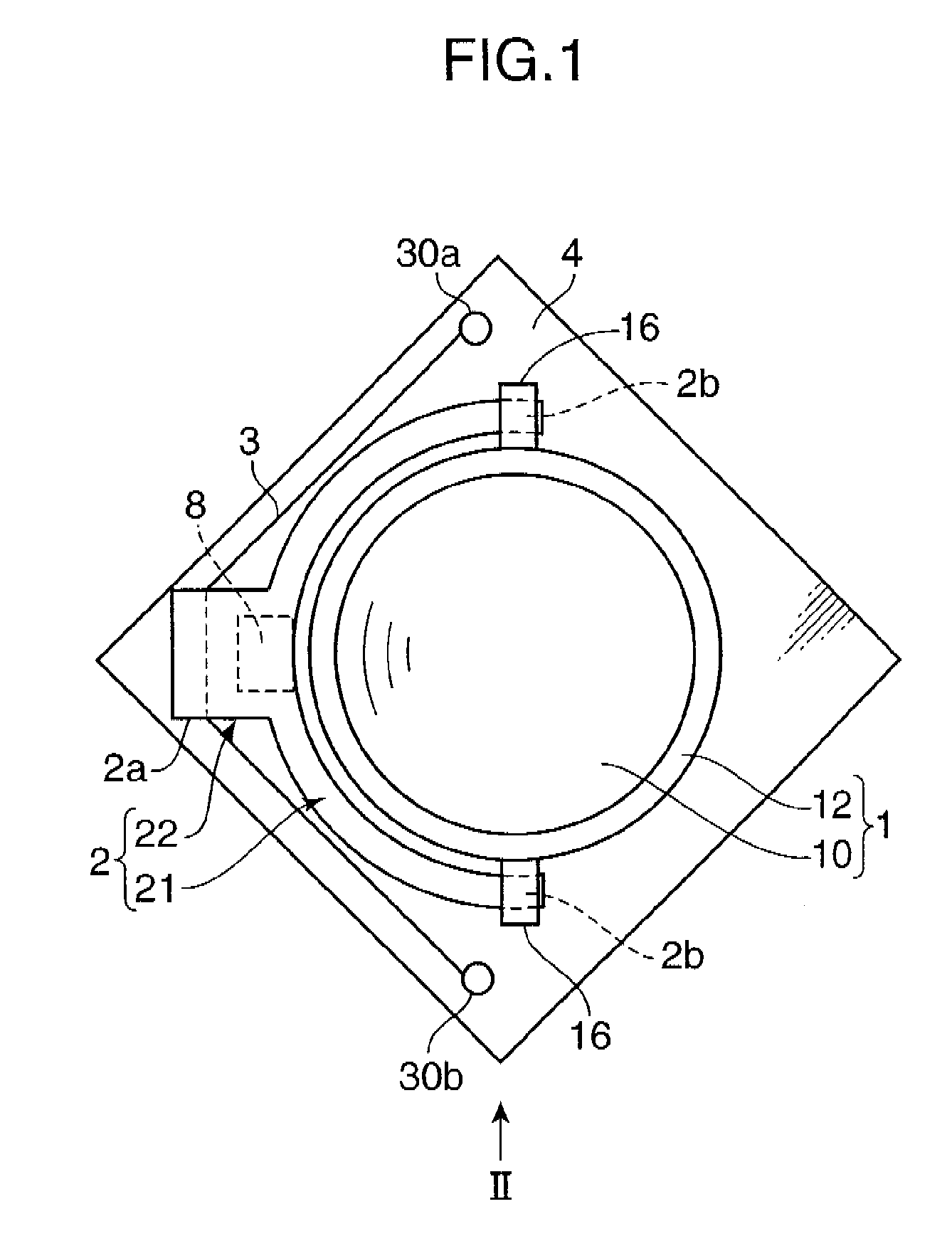
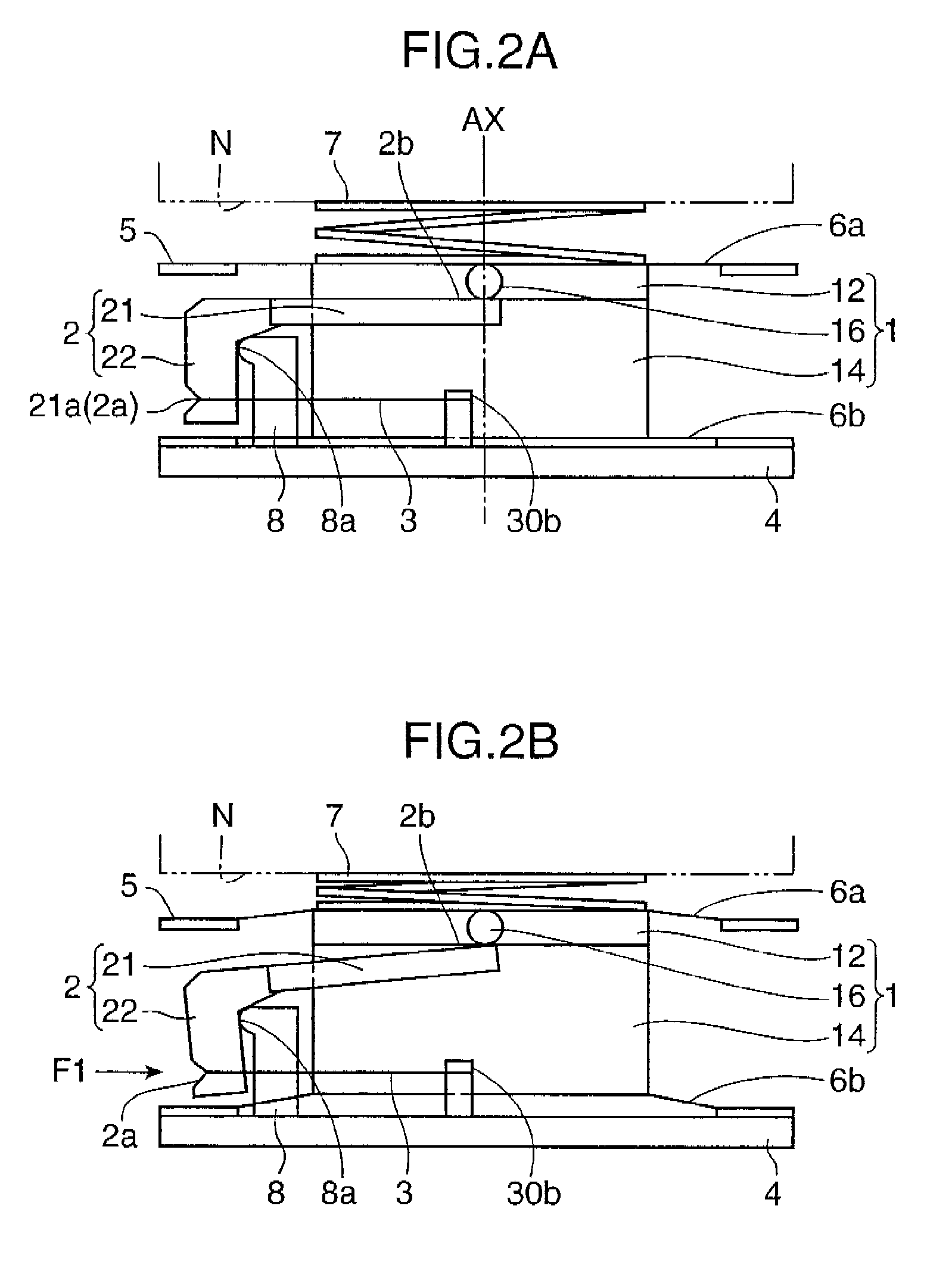
[0024]FIGS. 1 through 2B are diagrams schematically showing a primary part of a lens driving device in accordance with the first embodiment of the invention. FIG. 1 is a plan view of the lens driving device, and FIGS. 2A and 2B are side views respectively showing the lens driving device.
[0025]The lens driving device primarily includes a lens unit 1 as a driven member, a lever member 2 for moving the lens unit 1 in an optical axis AX direction, i.e., a first axis direction, an SMA actuator 3, abase member 4, a top plate 5, parallel-plate springs 6a and 6b, and a bias spring 7. The lens unit 1 and the relevant parts are mounted on the base member 4. In FIG. 1, the top plate 5, and the parallel plate springs 6a and 6b are not illustrated for simplifying the description. The lens driving device is applied to a driving mechanism and a driving device.
[0026]The base member 4 is fixed to a member for mounting the lens driving device e.g. a frame or a mount substrate of a mobile phone. The b...
second embodiment
[0052]In this section, a lens driving device in accordance with the second embodiment of the invention is described. The basic arrangement of the second embodiment is substantially the same as that of the first embodiment. Accordingly, elements which are functionally common between the first embodiment and the second embodiment are indicated by the same reference numerals, detailed description thereof is omitted herein, and differences between the first embodiment and the second embodiment are described in detail. The same idea is also applied to the third embodiment.
[0053]FIGS. 5 and 6 are diagrams schematically showing the lens driving device in accordance with the second embodiment FIG. 5 is a plan view of the lens driving device, and FIG. 6 is a side view of the lens driving device, respectively. In FIGS. 5 and 6, a top plate 5 and parallel plate springs 6a and 6b are not illustrated for simplifying the description.
[0054]In the lens driving device, parts such as a lever member 2...
third embodiment
In this section, a lens driving device in accordance with the third embodiment of the invention is described.
[0057]FIG. 7 is a side view schematically showing the lens driving device in accordance with the third embodiment. In FIG. 7, a top plate 5 and parallel plate springs 6a and 6b are not illustrated for simplifying the description. The lens driving device in the third embodiment is substantially the same as the lens driving device in the second embodiment in a point that parts such as a lever member 2 for driving a lens unit 1 are provided in a pair or a set. The third embodiment, however, is different from the second embodiment in a point that the lens unit 1 is movable in two way directions along the optical axis AX without using the bias spring 7.
[0058]In the lens driving device having the above arrangement, whereas displacement output portions 2b of a first lever member 2A are moved toward the object side by actuation of a first SMA actuator 3A, displacement output portions...
PUM
| Property | Measurement | Unit |
|---|---|---|
| angle | aaaaa | aaaaa |
| displacement | aaaaa | aaaaa |
| moving force | aaaaa | aaaaa |
Abstract
Description
Claims
Application Information
 - R&D
- Intellectual Property
- Life Sciences
- Materials
- Tech Scout
- Unparalleled Data Quality
- Higher Quality Content
- 60% Fewer Hallucinations
Browse by: Latest US Patents, China's latest patents, Technical Efficacy Thesaurus, Application Domain, Technology Topic, Popular Technical Reports.
© 2025 PatSnap. All rights reserved.Legal|Privacy policy|Modern Slavery Act Transparency Statement|Sitemap|About US| Contact US: help@patsnap.com


