Driving mechanism, driving device, and lens driving device

a driving mechanism and lens technology, applied in the direction of instruments, printers, cameras, etc., can solve the problems of difficult to reduce the size and weight of the lens driving device, and achieve the effect of great and stably moving the driven member and reducing the size and weight thereo

Inactive Publication Date: 2009-02-05
KONICA MINOLTA OPTO
View PDF3 Cites 20 Cited by
  • Summary
  • Abstract
  • Description
  • Claims
  • Application Information

AI Technical Summary

Benefits of technology

[0009]In view of the above conventional examples, it is an object of the present invention to provide a driving mechanism, a driving device, and a lens driving device, provided with an SMA actuator, capable of greatly and stably moving a driven member, while reducing the size and the weight thereof.
[0010]A driving mechanism, a driving device, and a lens driving device according to an aspect of the invention includes a lever member. The lever member includes an arm portion for surrounding a part of a driven member in a side direction. The arm portion has a plurality of displacement output portions to be engaged with the driven member. The lever member is constructed in such a manner that a displacement amount of the displacement output portion in a predetermined first axis direction is set larger than a displacement amount of a displacement input portion to be generated by input of a moving force to be applied by a shape memory alloy actuator. The driving mechanism, the driving device, and the lens driving device enable to obtain a large displacement amount with a reduced size and a reduced weight, and stably move the driven member.

Problems solved by technology

In the arrangement of D3, although a certain lens moving amount is secured, it is difficult to reduce the size and the weight of the lens driving device, because loading a gear mechanism is necessary.

Method used


Image

  • Driving mechanism, driving device, and lens driving device
  • Driving mechanism, driving device, and lens driving device
  • Driving mechanism, driving device, and lens driving device

Examples


first embodiment

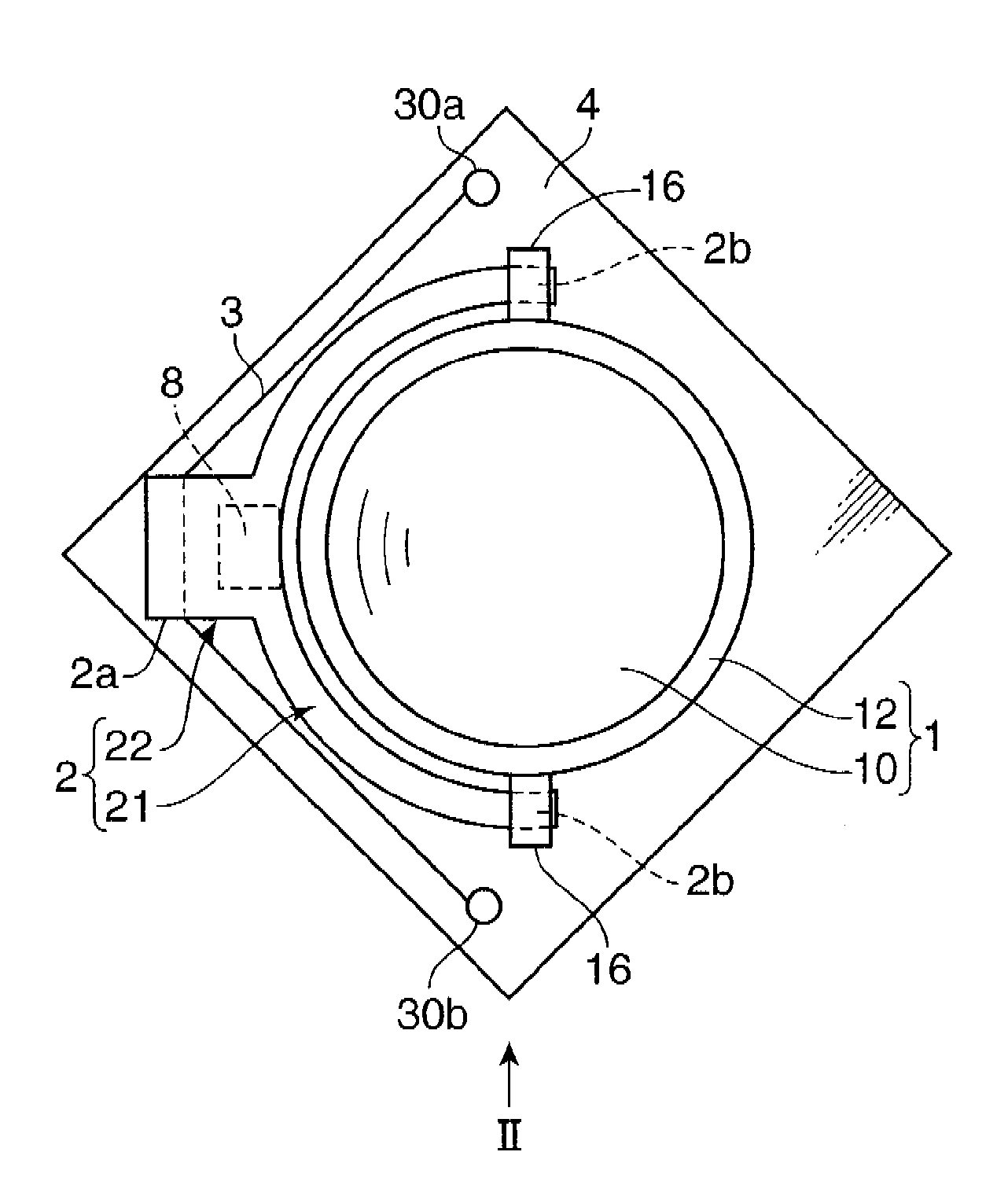
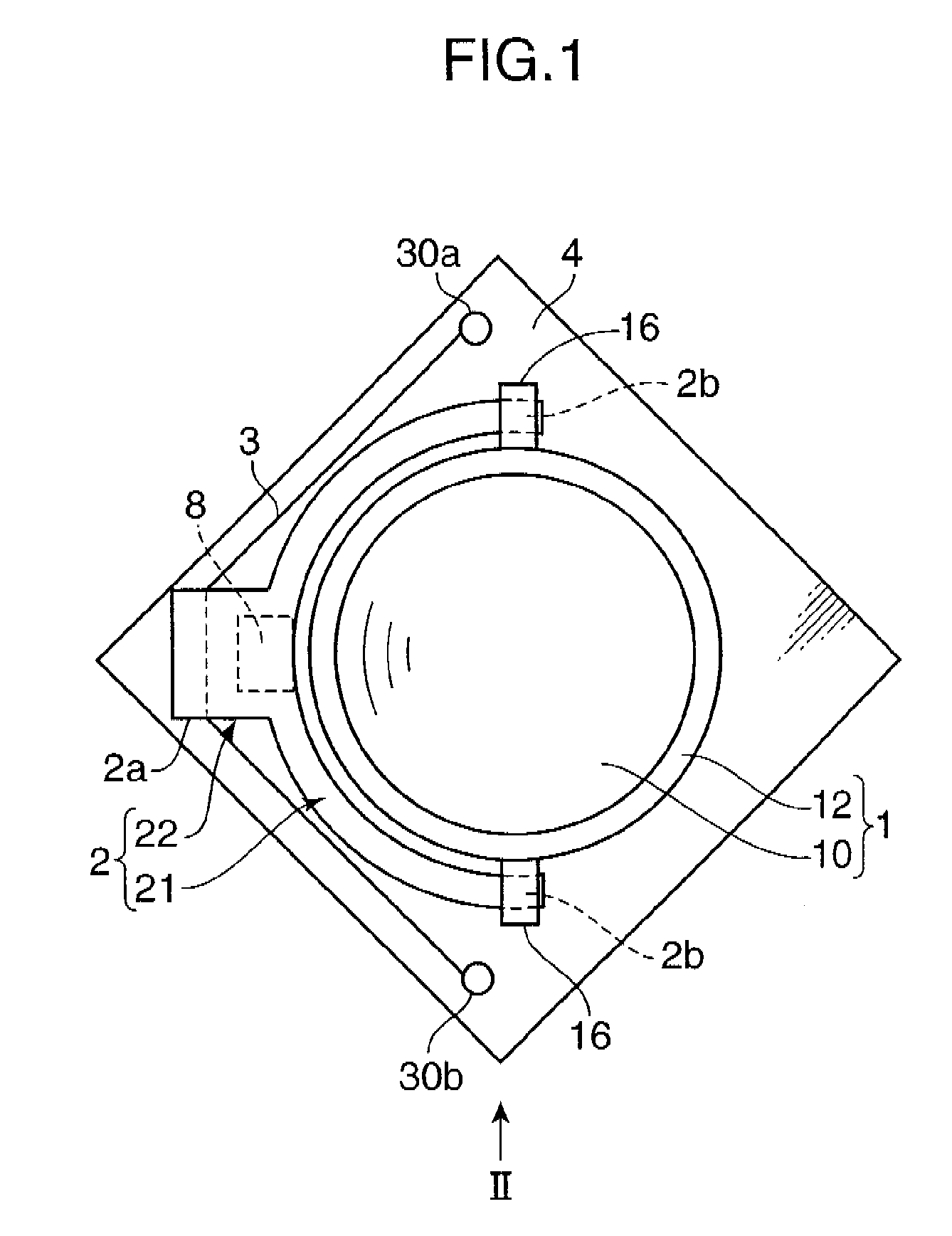
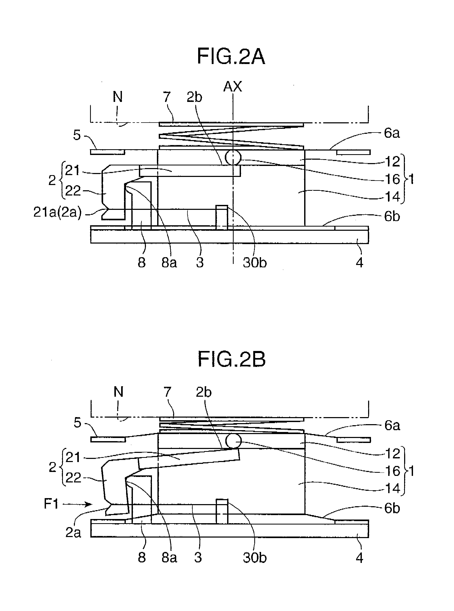
[0024]FIGS. 1 through 2B are diagrams schematically showing a primary part of a lens driving device in accordance with the first embodiment of the invention. FIG. 1 is a plan view of the lens driving device, and FIGS. 2A and 2B are side views respectively showing the lens driving device.

[0025]The lens driving device primarily includes a lens unit 1 as a driven member, a lever member 2 for moving the lens unit 1 in an optical axis AX direction i.e. a first axis direction, an SMA actuator 3, abase member 4, a top plate 5, parallel-plate springs 6a and 6b, and a bias spring 7. The lens unit 1 and the relevant parts are mounted on the base member 4. In FIG. 1, the top plate 5, and the parallel plate springs 6a and 6b are not illustrated for simplifying the description. The lens driving device is applied to a driving mechanism and a driving device.

[0026]The base member 4 is fixed to a member for mounting the lens driving device e.g. a frame or a mount substrate of a mobile phone. The bas...

second embodiment

[0054]In this section, a lens driving device in accordance with the second embodiment of the invention is described. The basic arrangement of the second embodiment is substantially the same as that of the first embodiment. Accordingly, elements which are functionally common between the first embodiment and the second embodiment are indicated by the same reference numerals, detailed description thereof is omitted herein, and differences between the first embodiment and the second embodiment are described in detail. The same idea is also applied to the third embodiment.

[0055]FIGS. 5 and 6 are diagrams schematically showing the lens driving device in accordance with the second embodiment FIG. 5 is a plan view of the lens driving device, and FIG. 6 is a side view of the lens driving device, respectively. In FIGS. 5 and 6, a top plate 5 and parallel plate springs 6a and 6b are not illustrated for simplifying the description.

[0056]In the lens driving device, parts such as a lever member 2...

third embodiment

[0059]In this section, a lens driving device in accordance with the third embodiment of the invention is described.

[0060]FIG. 7 is a side view schematically showing the lens driving device in accordance with the third embodiment. In FIG. 7, a top plate 5 and parallel plate springs 6a and 6b are not illustrated for simplifying the description. The lens driving device in the third embodiment is substantially the same as the lens driving device in the second embodiment in a point that parts such as a lever member 2 for driving a lens unit 1 are provided in a pair or a set. The third embodiment, however, is different from the second embodiment in a point that the lens unit 1 is movable in two way directions along the optical axis AX without using the bias spring 7.

[0061]In the lens driving device having the above arrangement, whereas displacement output portions 2b of a first lever member 2A are moved toward the object side by actuation of a first SMA actuator 3A, displacement output po...


PUM


Abstract

A driving mechanism, a driving device, and a lens driving device includes a lever member. The lever member includes an arm portion for surrounding a part of a driven member in a side direction. The arm portion has a plurality of displacement output portions to be engaged with the driven member. The lever member is constructed in such a manner that a displacement amount of the displacement output portions in a predetermined first axis direction is set larger than a displacement amount of a displacement input portion to be generated by input of a moving force to be applied by a shape memory alloy actuator. The driving mechanism, the driving device, and the lens driving device enable to obtain a large displacement amount with a reduced size and a reduced weight, and stably move the driven member.

Description

[0001]This application is based on Japanese Patent Application No. 2007-202093 filed on Aug. 2, 2007, the contents of which are hereby incorporated by reference.BACKGROUND OF THE INVENTION[0002]1. Field of the Invention[0003]The present invention relates to a driving mechanism for driving a lens unit constituting an image pickup optical system in e.g. a camera phone for zoom control, focus control, or a like control, as well as a driving device incorporated with the driving mechanism, and a lens driving device incorporated with the driving mechanism.[0004]2. Description of the Related Art[0005]In recent years, a high-resolution image pickup device has been developed. For instance, the number of pixels of an image sensor to be loaded in a camera phone or a like device has been spectacularly increased. As the high-resolution image pickup device has been developed, a focus function, a zoom function, or a like function has been demanded, in addition to a basic function i.e. an image sho...

Claims


Application Information

Patent Timeline
Patent Type & Authority Applications(United States)
IPC IPC(8): G02B15/14
CPCG03B3/10F03G7/065
Inventor NODA, ATSUHIROMATSUO, TAKASHI
Owner KONICA MINOLTA OPTO
Why Eureka
Try Eureka