Flow meter

a flow meter and flow rate technology, applied in the field of flow meters, can solve the problem of relatively high cost of electromagnetic flow meters, and achieve the effect of reducing costs

Active Publication Date: 2010-02-23
ABB LTD
View PDF50 Cites 7 Cited by
  • Summary
  • Abstract
  • Description
  • Claims
  • Application Information

AI Technical Summary

Benefits of technology

[0006]The present invention aims to provide at least an alternative type of electromagnetic flow meter which can be made at lower cost than currently available flow meters.
[0014]In one embodiment, the cross-sectional area of the measuring section in a direction transverse to the flow path divided by the cross-sectional area of the flow conduit in a direction transverse to the flow path is less than 70%. In one embodiment, the cross-sectional area of the measuring section may cover less than around 50% of the cross-sectional area of the flow conduit. This may be useful in a low flow rate system or to increase the uniformity of the magnetic field in the measuring section.
[0015]If desired an electrostatic screen may be provided integrally with or coupled to the insert for providing screening and structural stability to the insert.
[0016]Preferably, the insert is manufactured by moulding or extrusion, for example by injection moulding, transfer moulding or rotational moulding. Moulding the flow meter insert, from a material such as a plastics or rubber material may allow non-circular flow meter inserts to be provided that are lightweight and economical but that are strong and robust enough to maintain their integrity under fluid pressure. In one embodiment, the insert may be manufactured substantially from a thermoplastic material; for example, the insert may be manufactured from a glass-loaded plastics material. In another embodiment, the insert may be manufactured substantially from a thermoset material.
[0019]According to another aspect, the present invention provides an electromagnetic flow meter comprising: i) an inlet for receiving fluid flowing along a flow conduit, ii) an outlet in fluid communication with said inlet for outputting fluid that flows through the flow meter; iii) a measuring section positioned between, and in fluid communication with, said inlet and outlet; iv) a single coil positioned adjacent one side of said measuring section for generating a magnetic field across said measuring section; and v) electrodes for sensing electric fields generated by fluid flow through said magnetic field in said measuring section; wherein said single coil and said electrodes are arranged so that the integral of a weight function, which defines the sensitivity of the flow meter to fluid velocity through different parts of the measuring section, over a first half of said measuring section closest to said coil, is between 0.4 and 1.3 times the integral of the weight function over the other half of the measuring section. The inventors have found that designing the geometries of the electrodes and the coil to meet the above relationship results in a flow meter that can provide accurate flow measurements for many applications.
[0022]Preferably, the insert is back-potted on insertion into the flow conduit. Back-potting may allow the insert to be supported and stabilized within the conduit and hence may increase the reliability of the flow measurements.

Problems solved by technology

However, the cost of electromagnetic flow meters is relatively high mainly due to the materials used in their construction and necessarily high labour costs.

Method used


Image

  • Flow meter
  • Flow meter
  • Flow meter

Examples


embodiment 1

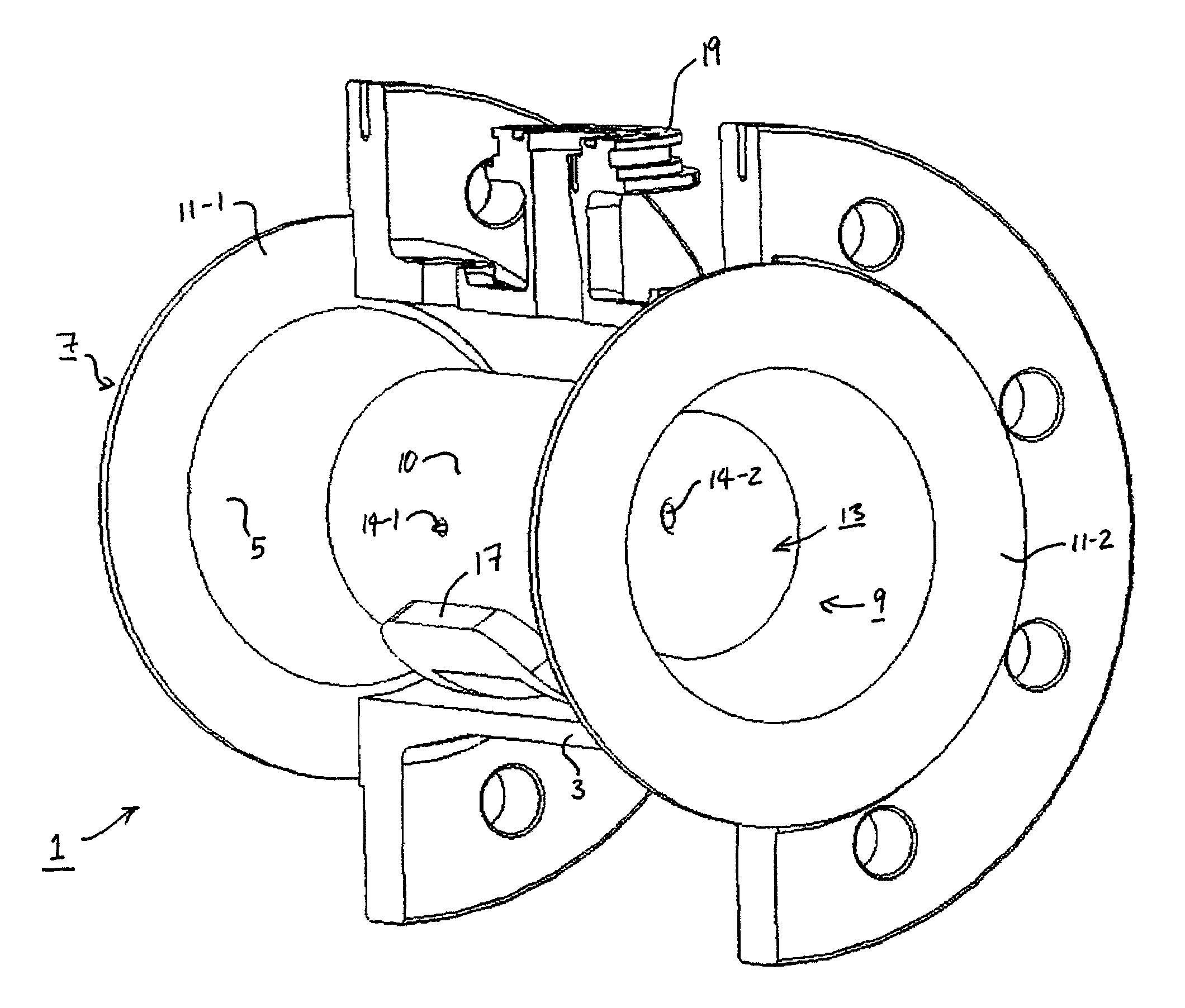
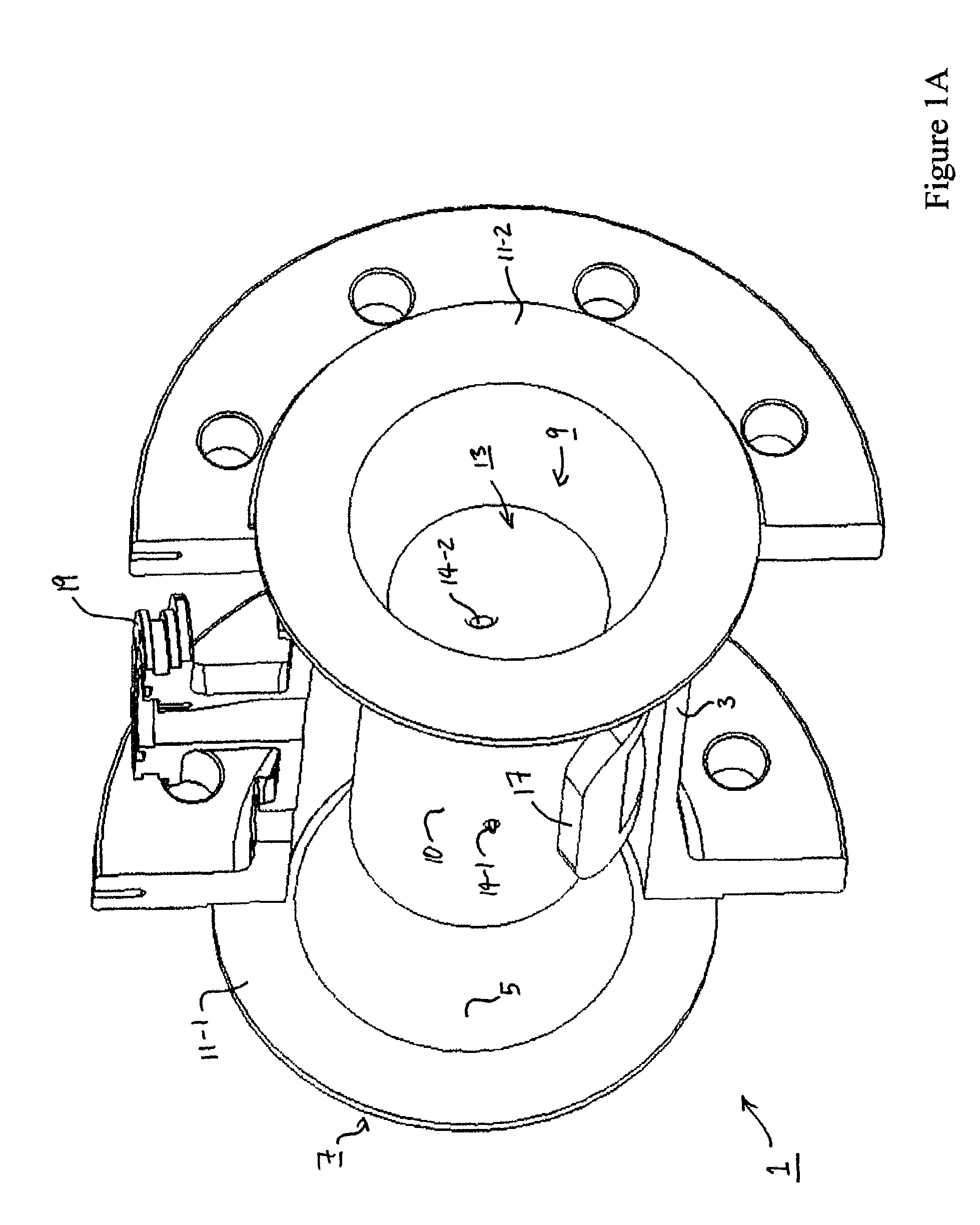
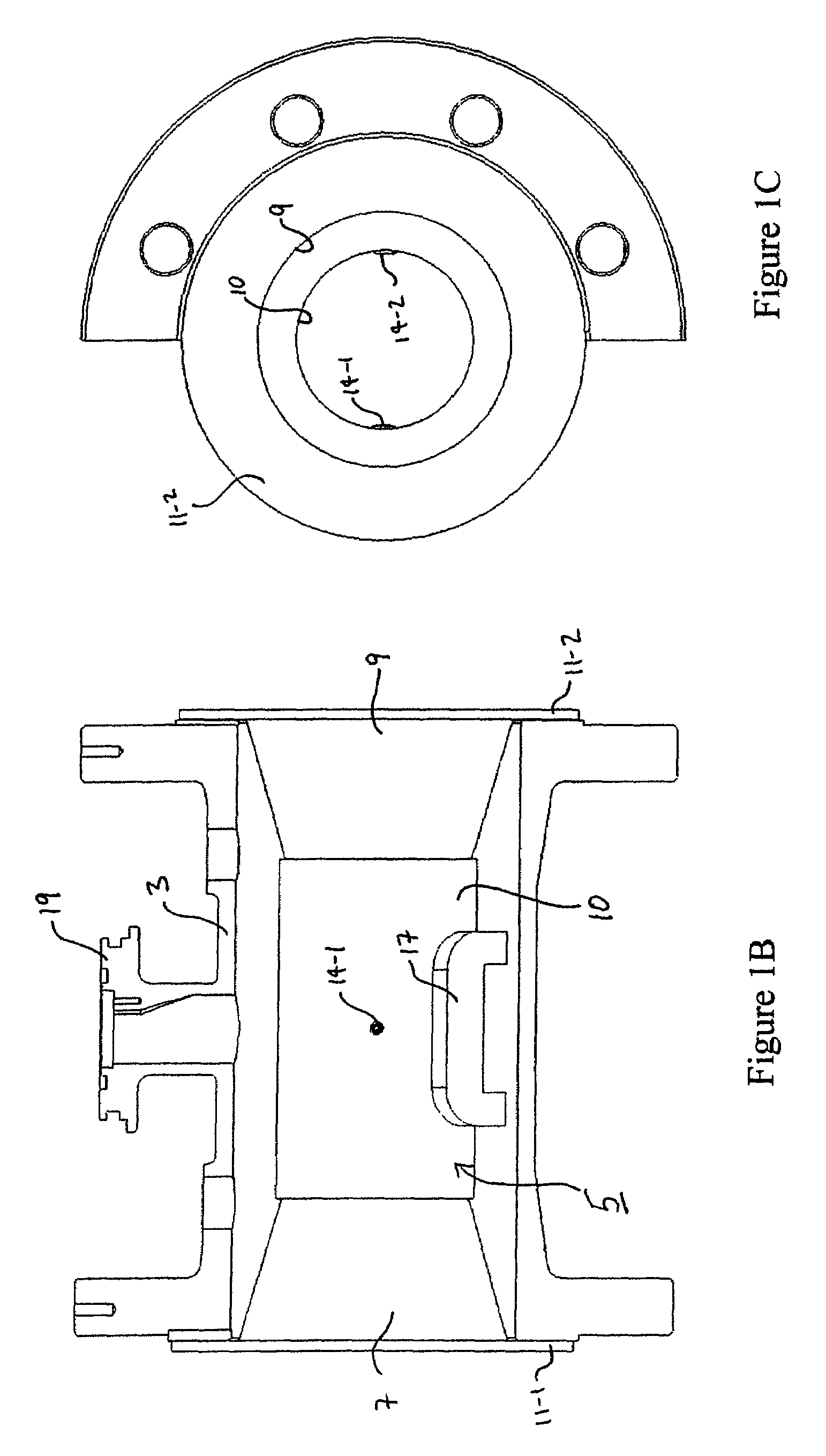
[0038]FIGS. 1 and 2 illustrate an electromagnetic flow meter 1 embodying the present invention. The flow meter 1 has a flow conduit 3 (made in this embodiment of Carbon Steel) which is cut in half to illustrate the form of an elongate insert 5 that is longitudinally inserted within the conduit 3. The insert 5 includes an inlet section 7, an outlet section 9 and a central measuring section 10, all of substantially circular cross-section. The dimensions of the inlet 7 and the outlet 9 are such that these sections of the insert 5 just fit within the flow conduit 3. In this embodiment, the insert has flanges 11-1 and 11-2 at each end (one of which may be detachable to facilitate insertion of the insert 5 within the flow conduit 3) that hold the insert securely within the flow conduit 3. The inner walls of the insert 3 define a central bore 13 for the passing of the fluid and means in the form of electrodes 14-1 and 14-2, for detecting electrical potential of the fluid passing through th...

second embodiment

[0050]FIGS. 4 and 5 illustrate an alternative design of electromagnetic flow meter embodying the present invention. In these Figures, the same reference numerals have been used to designate like elements.

[0051]The main difference between the flow meter of this embodiment and the flow meter of the first embodiment is that the measuring section 10 has an octagonal cross-section in a direction transverse to the fluid flow. Further, in this embodiment, as illustrated in FIG. 5B, the single coil 17 surrounds a lower segment of the measuring section 10 having a segment angle (θ) of approximately 140 degrees.

[0052]In this embodiment, the insert may be made from any one of: polytetrafluoroethylene (PTFE), ethylene-tetrafluoroethylene (ETFE), polypropylene (PP), polyvinylchloride (PVC), polyethylene terephthalate (PET), acrylonitrile butadiene styrene (ABS), polyethylene (PE), polybutylene terephtalate (PBT), polyoxymethylene (POM), polyphenylene sulphide (PPS) polyetherethere ketone (PEEK),...


PUM

PropertyMeasurementUnit
angleaaaaaaaaaa
angleaaaaaaaaaa
diameteraaaaaaaaaa

Abstract

An electromagnetic flow meter for measuring flow rate of a fluid passing therethrough includes a conduit defining a fluid inlet, a fluid outlet and a measuring section positioned between the inlet and the outlet. The flow meter also includes a single coil for generating a magnetic field across the measuring section and electrodes for detecting induced electrical potential due to the fluid passage. The flow meter also includes means for conditioning the flow through the measuring section. The combination of the single coil and the flow conditioning means provides a flow meter with a desired level of accuracy. The single coil and the electrodes may be arranged so that the integral of a weight function, which defines the sensitivity of the flow meter to fluid velocity through different parts of the measuring section, over the first half of a measuring section closest to the coil is between 0.4 and 1.3 times the integral of the weight function over the other half of the measuring section.

Description

CROSS-REFERENCE TO RELATED APPLICATIONS[0001]This application claims priority of Great Britain Application No. 0616505.4, filed Aug. 18, 2006, which is hereby incorporated herein in its entirety by reference.FIELD OF THE INVENTION[0002]The present invention relates to flow meters and in particular to electromagnetic flow meters and the manufacture thereof.BACKGROUND OF THE INVENTION[0003]Electromagnetic flow meters, and their modes of operation, are well known. In use, an electromagnetic field is generated whose lines of flux are mutually perpendicular to the longitudinal axis of the flow tube through which the fluid to be metered is conducted and to the transverse axis along which the electrodes are located at diametrically opposed positions with respect to the tube. The operating principles are based on Faraday's Law of induction, which states that the voltage induced across any conductor as it moves at right angles through a magnetic field will be proportional to the velocity of ...

Claims


Application Information

Patent Timeline
Patent Type & Authority Patents(United States)
IPC IPC(8): G01F1/60
CPCG01F1/586Y10T29/4902G01F1/588
Inventor LINCOLN, DAVIDARMITAGE, MICHAEL
Owner ABB LTD
Why Eureka
Try Eureka