
Safety cement plug launch system

a safety cement and launch system technology, applied in the direction of fluid removal, sealing/packing, borehole/well accessories, etc., can solve the problems of unsafe activity, use of electrical devices, system may be too cumbersome and complex,

Active Publication Date: 2010-02-23
BAKER HUGHES INC
View PDF17 Cites 1 Cited by
  • Summary
  • Abstract
  • Description
  • Claims
  • Application Information

AI Technical Summary

Benefits of technology

The present patent is about a system for remotely launching a cement plug from a cement head. The system includes a pneumatic line connected to the cement head, a plurality of pressure regulators for controlling pressure in the pneumatic line, and means for remotely releasing a device used to retain a first cement plug in the cement head. The system also includes means for remotely opening and closing valves above and below the first cement plug to ensure safe launching of the cement plug. The technical effect of the system is to provide a reliable and safe way to launch cement plugs from a cement head.

Problems solved by technology

This can be a potentially unsafe activity as the cement head is often located on a derrick high above the wellhead.
The cement head is often located in an area considered a zone zero in some regions, such as the North Sea, which is considered hazardous due to the possibility of combustible gases being present.
The location of the cement head in a zone zero prevents the use of an electrical device to actuate the valves or manipulate the retaining devices because a spark from the electrical device could ignite combustible gas that may be present.
It would be beneficial to provide a system or apparatus that may be used to remotely launch a cement plug from the cement head, but the location of the cement head in a zone zero may prevent the use of an electrical device to launch the cement plug.
However, such a system may be too cumbersome and complex if a pneumatic line needs to be connected to each valve and each retaining device of the cement head.
The manual operation of the cement head may also be potentially hazardous if the valves and the releasing of the retention device are not operated properly.
The premature closure of a valve or failure to remove the retaining device may cause an accident to occur because of the high pressure slurry being pumped into the cement head.

Method used


Image

  • Safety cement plug launch system
  • Safety cement plug launch system
  • Safety cement plug launch system

Examples


Embodiment Construction

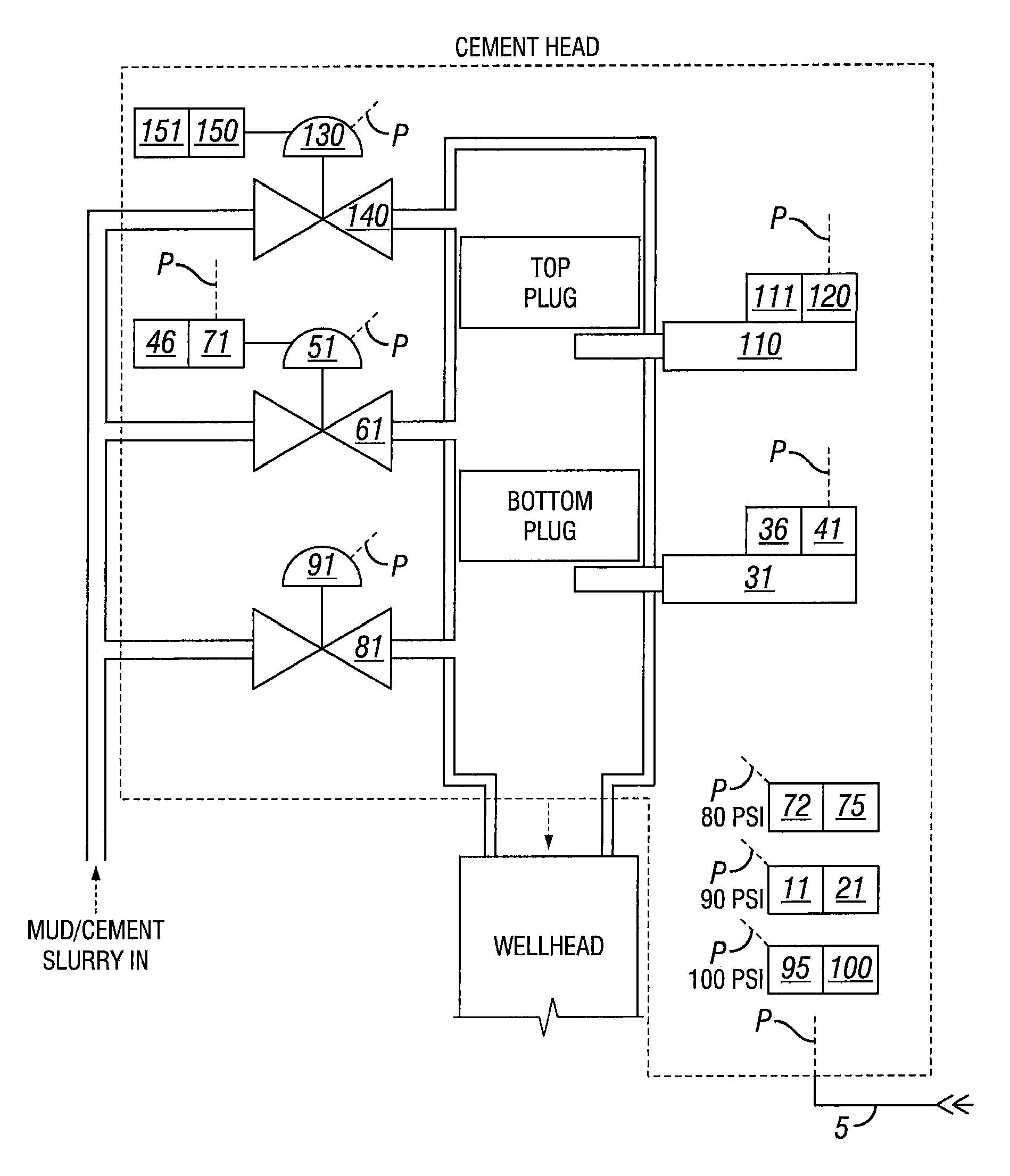
[0040]Illustrative embodiments of the invention are described below as they might be employed in system that automates the launching of a cement plug from a cement head. In the interest of clarity, not all features of an actual implementation are described in this specification. It will of course be appreciated that in the development of any such actual embodiment, numerous implementation-specific decisions must be made to achieve the developers' specific goals, such as compliance with system-related and business-related constraints, which will vary from one implementation to another. Moreover, it will be appreciated that such a development effort might be complex and time-consuming, but would nevertheless be a routine undertaking for those of ordinary skill in the art having the benefit of this disclosure.

[0041]Further aspects and advantages of the various embodiments of the invention will become apparent from consideration of the following description and drawings.

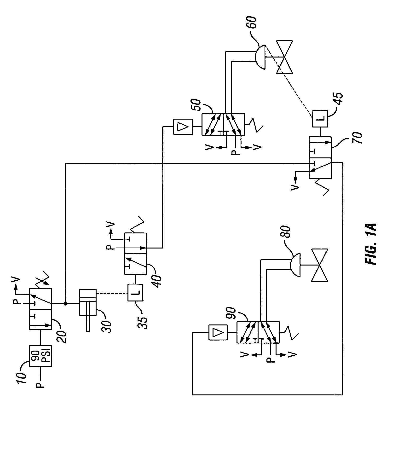
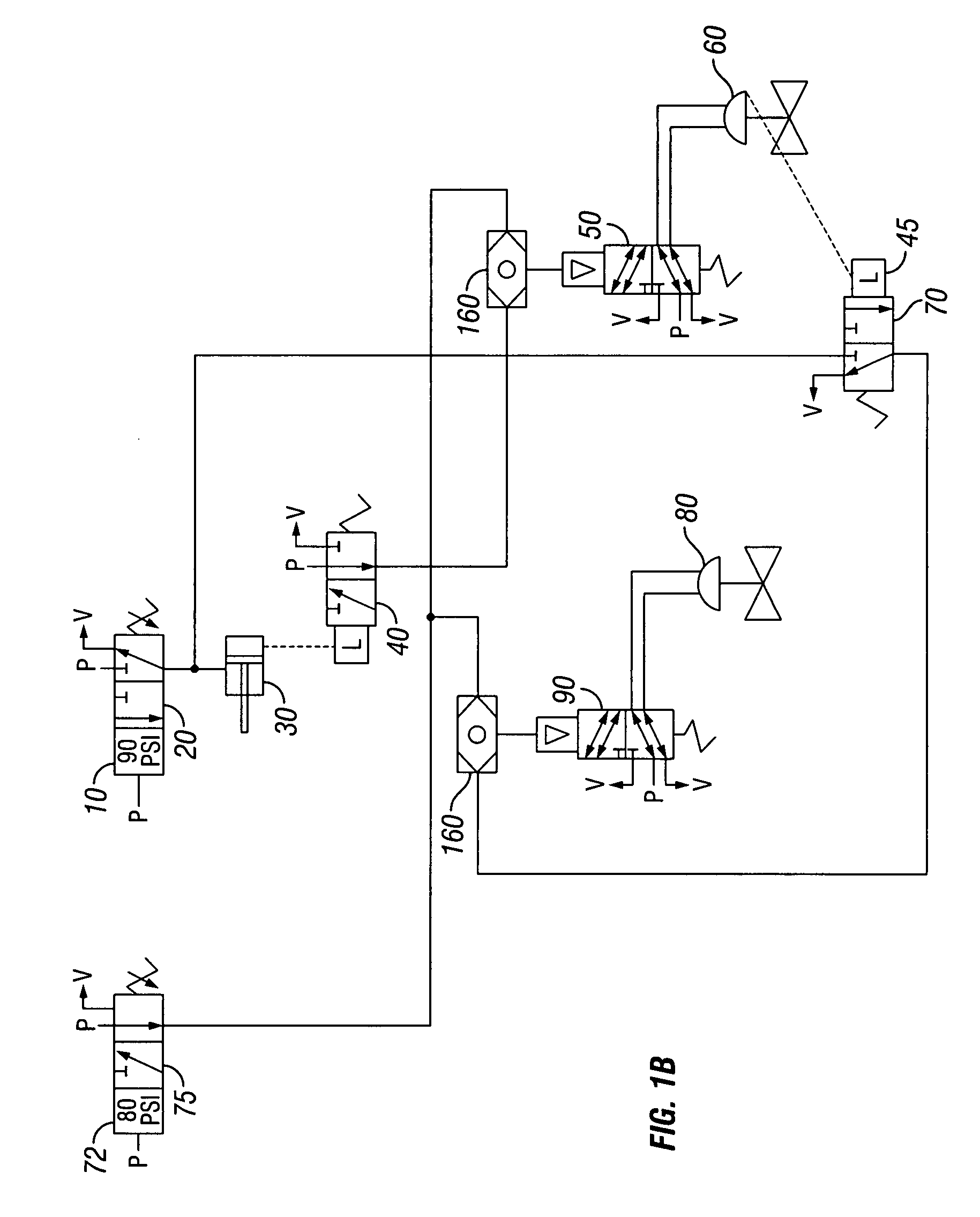
[0042]FIG. 1A sh...


PUM


Abstract

A system and method for using a pneumatic line to automate the launch a cement plug from a cement head. The pneumatic line is in communication with the valves and retaining devices normally found on a typical cement head. The system ensures that the proper sequence of opening and closing valves in combination with the removal of the retaining device is used to safely launch a cement plug from the cement head. The pressure in the single pneumatic line may be varied to launch multiple cement plugs from a cement head. The system may be used to remotely launch a cement plug from a cement head. A wireless remote may be used to regulate the pressure in the pneumatic line to launch cement plugs from the cement head as desired.

Description

BACKGROUND OF THE INVENTION[0001]1. Field of the Invention[0002]The present invention relates generally to a system and method for using a pneumatic line to automate the launch of a cement plug or multiple cement plugs from a cement head. The system ensures that the proper sequence of opening and closing valves in combination with the removal of a retaining device is done to safely launch a cement plug. The present invention discloses varying the pressure in a single pneumatic line to launch multiple cement plugs from a cement head. A wireless remote may be used to regulate the pressure in the pneumatic line to launch cement plugs from the cement head as desired from a remote location.[0003]2. Description of the Related Art[0004]Oil and gas wells typically include steel casing or steel tubing, hereinafter steel casing, cemented into the wellbore to provide support to the wellbore and prevent the wellbore from collapsing. The cement casing is important to support the wellbore formati...

Claims


Application Information

Patent Timeline
Patent Type & Authority Patents(United States)
IPC IPC(8): E21B33/16
CPCE21B33/05E21B33/16E21B34/16
Inventor CARLSON, BRADLEY T.
Owner BAKER HUGHES INC
Learn More