Aerial vehicle launching system and method

a technology for aerial vehicles and launch systems, applied in the direction of unmanned aerial vehicles, vehicles, launching/towing gear, etc., can solve the problems of difficult, costly, difficult, etc., to redesign an aircraft to have a higher level, and many problems for aircra

Active Publication Date: 2010-02-23
RAYTHEON CO
View PDF8 Cites 72 Cited by
  • Summary
  • Abstract
  • Description
  • Claims
  • Application Information

AI Technical Summary

Problems solved by technology

Aerial vehicles, particularly smaller unmanned aerial vehicles (UAVs), often face problems due to wind gusts, foreign object damage (FOD), and other risk factors inherent in rolling takeoffs.
These risks are especially significant in situations where the propeller of the UAV has a low ground clearance and where there are loose rocks and other debris on the runway surface.
Since it is often difficult, costly, or otherwise impractical to redesign an aircraft to have a higher propeller clearance from the ground and / or to remove all debris from a runway surface, one conventional solution to address risks associated with traditional rolling takeoffs is to implement a launch system for the aerial vehicle.
However, conventional launching systems and methods present a number of significant disadvantages.
One disadvantage for a directly restrained UAV is that there may not be suitable structural hard-points on the UAV for such a system to operate properly.
For example, hard-point attachment sites on the aircraft may not have sufficient structural integrity to resist the shock of a launch from a launches without failing and causing the aircraft to be damaged.
Another disadvantage of conventional systems is that they may be unable to prevent significant transient movements after release of the aircraft from the launcher, which can result in faulty launch of the vehicle.
Yet another disadvantage is that conventional launch systems can transfer / impart shock, thereby damaging the aircraft or its control systems; particularly when the aircraft is attached to the launch system via its wings or other relatively delicate control surfaces.
Another disadvantage is that conventional launch systems can transfer / impart vibration, thereby damaging or affecting an aircraft's sensors, navigation systems, electronics, or other avionics.
Still another disadvantage is that the propeller of the UAV may not have sufficient clearance with respect to the launch system.
Yet another disadvantage is that a substantially direct connection between the restrained device and the restraining device may result in the two binding and preventing their decoupling during a launch.
Consequently, it is often expensive and impractical to launch UAVs of varying configurations using existing launch systems, since each aircraft would require a dedicated launch system.
Furthermore, conventional launch systems are often hindered by heavy aerial vehicle weights and the need for variable takeoff speeds depending on weather conditions.

Method used


Image

  • Aerial vehicle launching system and method
  • Aerial vehicle launching system and method
  • Aerial vehicle launching system and method

Examples


Embodiment Construction

[0018]The following representative descriptions of the present invention generally relate to exemplary embodiments and the inventors' conception of the best mode, and are not intended to limit the scope, applicability or configuration of the invention in any way. Rather, the following description is intended to provide convenient illustrations for implementing various embodiments of the invention. As will become apparent, changes may be made in the function and / or arrangement of any of the elements described in the disclosed exemplary embodiments without departing from the spirit and scope of the invention.

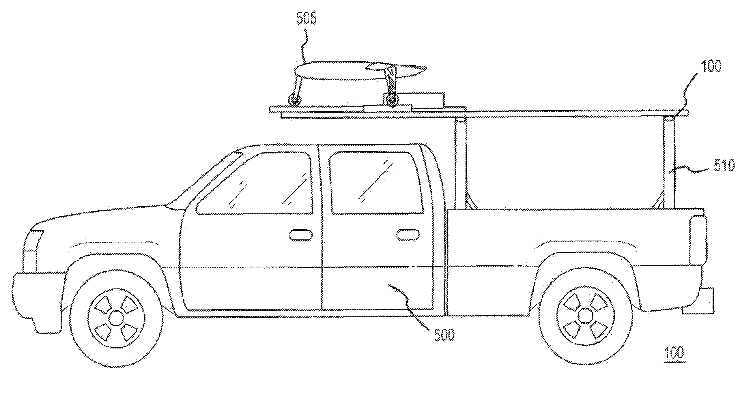
[0019]Various representative implementations of the present invention may be applied to any system for launching aerial vehicles. It will be appreciated that additional features may be readily adapted, extended, or otherwise applied to future vehicle launching system designs. Accordingly, it will be further understood that the present invention is more generally directed to the ge...


PUM


Abstract

An aerial vehicle launching system includes a launch platform and a restraint system coupled to the launch platform. The restraint system has at least one passive restraint suitably adapted to indirectly restrain an aerial vehicle. The restraint system is configured to coordinate the uniform retention and release of the passive restraint in order to launch the aerial vehicle.

Description

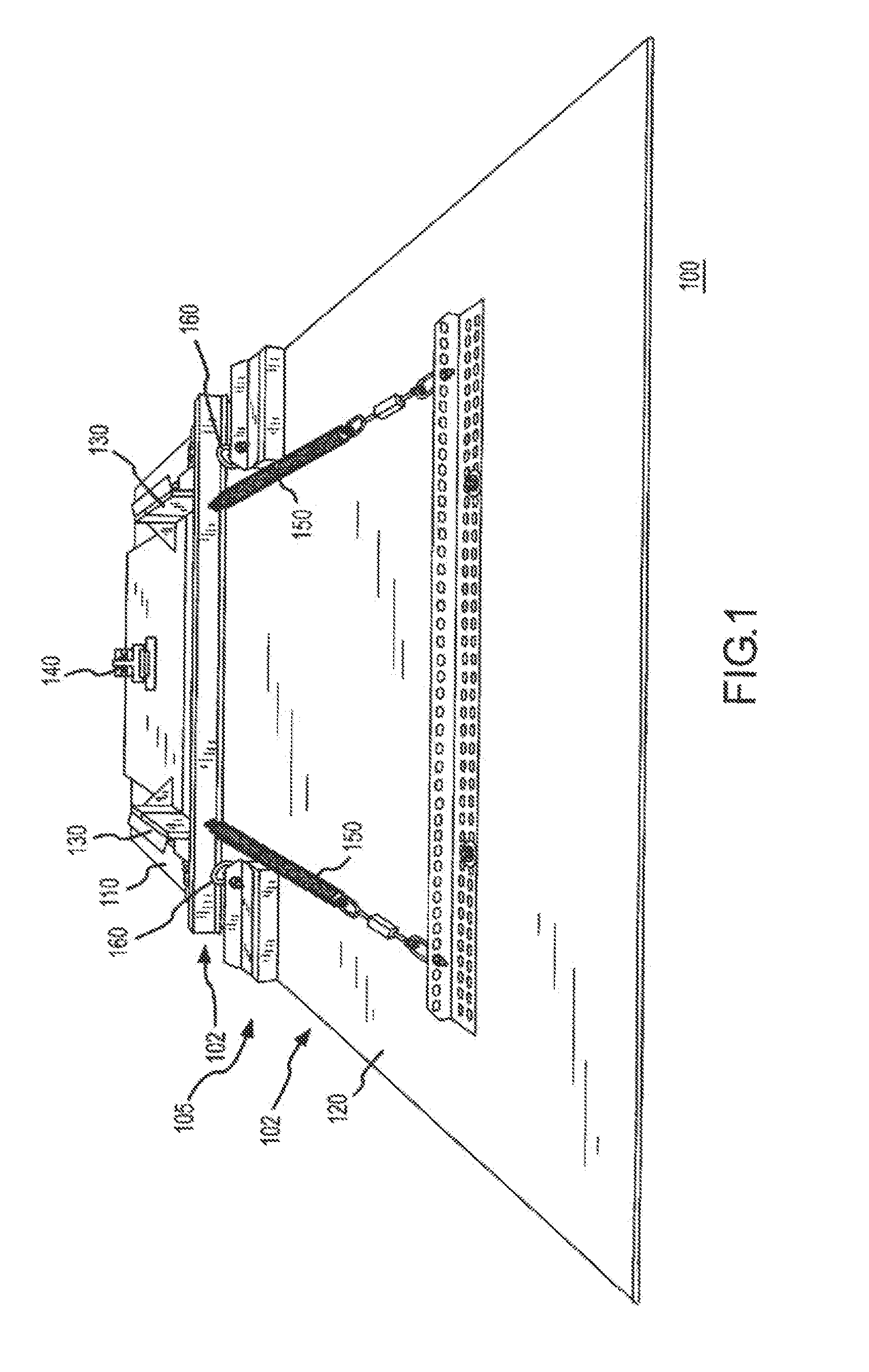
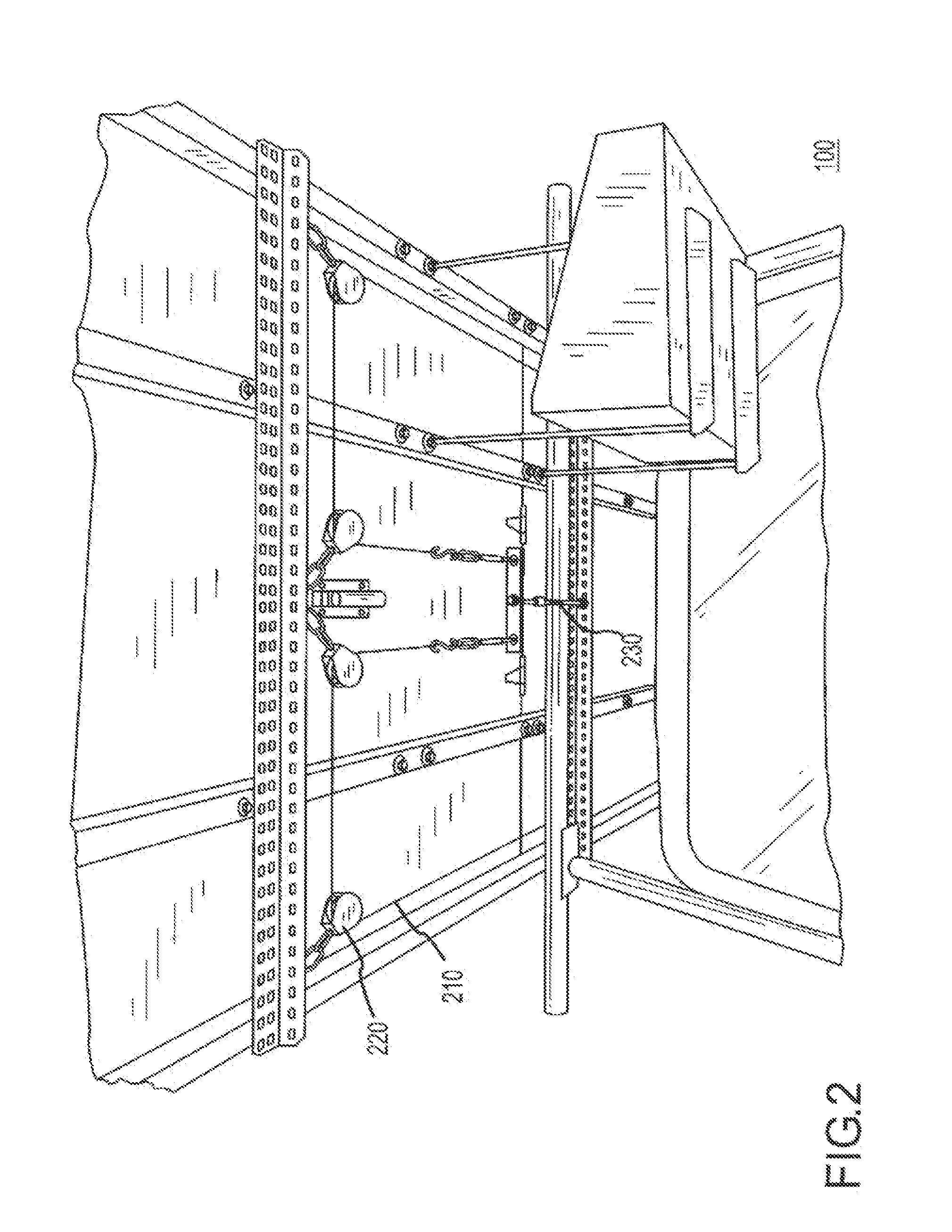
FIELD OF THE INVENTION[0001]The present invention generally concerns systems and methods for launching aerial vehicles; and more particularly, representative and exemplary embodiments of the present invention generally relate to systems, devices and methods for launching unmanned aerial vehicles (UAVs).BACKGROUND OF INVENTION[0002]Aerial vehicles, particularly smaller unmanned aerial vehicles (UAVs), often face problems due to wind gusts, foreign object damage (FOD), and other risk factors inherent in rolling takeoffs. These risks are especially significant in situations where the propeller of the UAV has a low ground clearance and where there are loose rocks and other debris on the runway surface.[0003]Since it is often difficult, costly, or otherwise impractical to redesign an aircraft to have a higher propeller clearance from the ground and / or to remove all debris from a runway surface, one conventional solution to address risks associated with traditional rolling takeoffs is to ...

Claims


Application Information

Patent Timeline
Patent Type & Authority Patents(United States)
IPC IPC(8): B64F1/10
CPCB64F1/10B64C2201/084B64C2201/208B64U70/70B64U80/86
Inventor HANZLICK, PATRICK T.LANGE, JOSHUA J.
Owner RAYTHEON CO
Why Eureka
Try Eureka